Multi-layer vacuum pneumatic elevator
A pneumatic elevator and vacuum technology, which is used in elevators, lifts, transportation and packaging in buildings, etc., can solve the problems of high requirements for wells, high use and maintenance costs, and large floor space, so as to reduce energy consumption and improve The effect of pumping efficiency
- Summary
- Abstract
- Description
- Claims
- Application Information
AI Technical Summary
Problems solved by technology
Method used
Image

Examples
Embodiment Construction
[0019] In order to describe the technical solution of the above invention in more detail, specific examples are listed below to demonstrate the technical effect; it should be emphasized that these examples are used to illustrate the present invention and not limit the scope of the present invention.
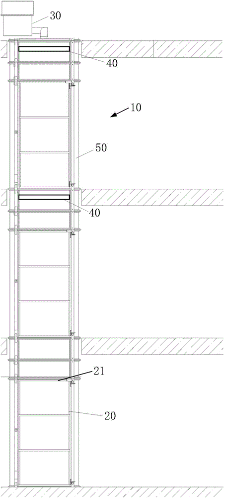
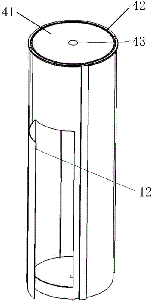
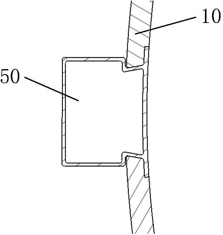
[0020] A kind of multi-storey vacuum pneumatic elevator provided by the present invention, such as Figure 1 to Figure 4 As shown, it includes a hoistway 10, a guide rail 11 arranged in the hoistway 10, a car 20 arranged in the hoistway 10 and capable of sliding up and down along the guide rail 11, and a vacuum suction device 30 installed on the top or outside of the hoistway 10, The top of the car 20 is provided with a circumferential sealing ring 21, and a retractable support rod (not shown in the figure) is respectively provided in the shaft 10 corresponding to the top of each floor. A sealed partition 40 , the partition 40 and the circumferential sealing ring 21 divide the ho...
PUM
 Abstract
Description
Claims
Application Information
 - Generate Ideas
- Intellectual Property
- Life Sciences
- Materials
- Tech Scout
- Unparalleled Data Quality
- Higher Quality Content
- 60% Fewer Hallucinations
Browse by: Latest US Patents, China's latest patents, Technical Efficacy Thesaurus, Application Domain, Technology Topic, Popular Technical Reports.
© 2025 PatSnap. All rights reserved.Legal|Privacy policy|Modern Slavery Act Transparency Statement|Sitemap|About US| Contact US: help@patsnap.com