Nozzle

A nozzle and float technology, applied in the field of nozzles, can solve the problems of high silicon core temperature, cauliflower shape and rough surface.

Active Publication Date: 2015-03-11
CHINA ENFI ENGINEERING CORPORATION +1
View PDF6 Cites 7 Cited by
  • Summary
  • Abstract
  • Description
  • Claims
  • Application Information

AI Technical Summary

Problems solved by technology

Generally, the gas velocity of the mixed gas nozzle can only change with the change of the gas volume. When the mixed gas flow rate is small, the flow velocity at the nozzle outlet is small, and the mixed gas cannot reach the top of the silicon rod, which affects the distribution of the thermal field in the furnace and causes the upper end of the silicon rod to be damaged. The local temperature is high, forming cauliflower-like polysilicon, and in severe cases, melting silicon phenomena such as burn-off will occur
[0003] The nozzles in the prior art cannot adjust the flow rate according to the gas volume, so as to meet

Method used


Image

  • Nozzle

Examples


Embodiment Construction

[0018] It should be noted that, in the case of no conflict, the embodiments in the present application and the features in the embodiments can be combined with each other. The present invention will be described in detail below with reference to the accompanying drawings and examples.

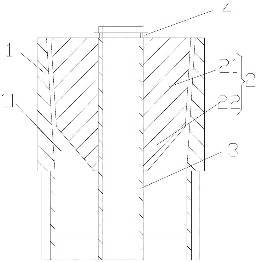
[0019] Such as figure 1 As shown, the nozzle of the embodiment of the present invention includes a nozzle body 1 and a float 2 , and a cavity 11 for fluid communication is arranged in the nozzle body 1 . The float 2 includes a float body 21 , the outer peripheral surface of the float body 21 and the inner peripheral surface of the cavity 11 form a communication gap for fluid to flow out. Wherein, the cavity 11 is conical, and the float 2 is movably arranged relative to the nozzle body 1 along the direction of the line connecting the inlet end of the cavity 11 and the outlet end of the cavity 11 and has a tendency to move toward the inlet end of the cavity 11 , the flow gap gradually increases...


PUM


Abstract

The invention provides a nozzle. The nozzle comprises a nozzle body and a floater, wherein a conical cavity which allows fluid circulation is formed inside the nozzle body; the floater comprises a floater body; a circulation gap from which the fluid flows out is formed by the outer circumferential surface of the float body and the inner circumferential surface of the cavity; the floater is movably arranged relative to the nozzle body in the direction of a connecting line of the inlet end of the cavity and the outlet end of the cavity and tends to move to the inlet end of the cavity; when the floater moves in the direction from the inlet end to the outlet end, the circulation gap is gradually enlarged. When the flow of the fluid entering the inlet end of the cavity is higher, the floater moves in the direction from the inlet end to the outlet end under the action of the impact force of the fluid, and the circulation gap is gradually enlarged, so that the flow speed is effectively decreased; when the flow of the fluid is lower, the circulation gap is smaller, so that the flow speed of the fluid flowing out of the circulation gap is guaranteed favorably, and the function of automatically regulating the flow speed by the nozzle according to the flow magnitude of the fluid is achieved.

Description

technical field [0001] The invention relates to a nozzle. Background technique [0002] In the field of polysilicon production, the reduction furnace is the core equipment for the production of polysilicon. The mixed gas mainly containing trichlorosilane and hydrogen enters the furnace cavity through the mixed gas nozzle, and the reaction is completed under high temperature and high pressure, and the formed silicon is deposited on the silicon core rod. . Generally, the gas velocity of the mixed gas nozzle can only change with the change of the gas volume. When the mixed gas flow rate is small, the flow velocity at the nozzle outlet is small, and the mixed gas cannot reach the top of the silicon rod, which affects the distribution of the thermal field in the furnace and causes the upper end of the silicon rod to be damaged. The local temperature is high, forming cauliflower-like polysilicon, and in severe cases, molten silicon phenomena such as burning flow occur. [0003] ...

Claims


Application Information

Patent Timeline
IPC IPC(8): C01B33/035
Inventor 孙强万烨严大洲汤传斌乔兵超
Owner CHINA ENFI ENGINEERING CORPORATION
Why Eureka
Try Eureka