A high-pressure waterproof self-stabilizing load testing device for deep soil layers
A technology of load testing and self-stabilization, applied in the direction of applying stable tension/compression to test material strength, on-site foundation soil survey, construction, etc. Problems such as soil bearing capacity and deformation characteristic test ability, to achieve the effect of increasing compressive capacity and strong anti-overturning ability
- Summary
- Abstract
- Description
- Claims
- Application Information
AI Technical Summary
Problems solved by technology
Method used
Image
Examples
Embodiment 1
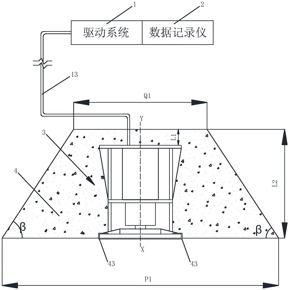
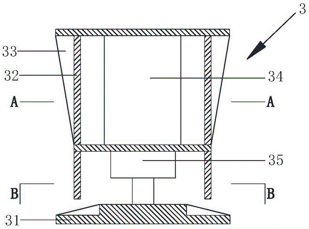
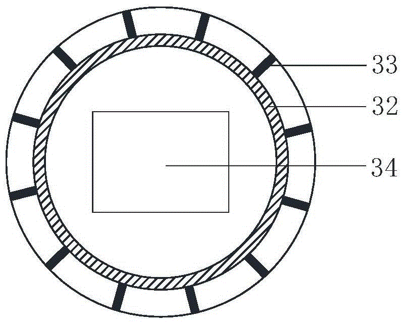
[0032] The structure of the load test device in this example is as follows: figure 1 As shown, it consists of a driving system 1, a data recorder 2, a load box 3 and a concrete self-stabilizing block 4. The data recorder 2 and the drive system 1 are connected to the load box 3 through the pipeline 13, collect load data and drive the load box 3 to run. The structure of the load box 3 in this example is as follows figure 2 , image 3 and Figure 4 As shown, it includes a pressure bearing plate 31, a box body 32, a hydraulic mechanism, a rib 33 and a sensor (not shown in the figure). The hydraulic mechanism of this example consists of an oil pump 34 and a jack 35, and the jack is installed on the symmetrical axis XY of the load box, as figure 1 As shown, the axis of symmetry XY is also the axis of symmetry of the concrete self-stabilizing block 4 of this example. figure 2 Among them, the pressure bearing plate 31 is made of a circular steel plate, in order to increase the ...
Embodiment 2
[0036] The load test device in this example has a structure such as Figure 5 As shown, the shape of the concrete self-stabilizing block 4 is a square prism concrete block, the upper and lower bottom surfaces of the concrete block are squares with a side length of P1, the height of the concrete block is L2, and the distance between the upper bottom surface and the load box is L1. The concrete block in this example also has a symmetrical structure, which coincides with the axis of symmetry XY of the load box. The load box structure of this example is the same as that of Example 1.
Embodiment 3
[0038] The load test device in this example has a structure such as Figure 6 As shown, the hydraulic mechanism is composed of three jacks. In this example, the pressure plate is made of circular steel plate. Due to the large area of the steel plate, ribs are added to prevent deformation during pressurization to strengthen the rigidity of the pressure plate. Depend on Figure 6 It can be seen that the three jacks are evenly distributed along the symmetrical axis of the bearing plate, and their piston rods are connected with the bearing plate to jointly push the bearing plate to move vertically. For other structures of this example, reference may be made to the description of the foregoing embodiments.
PUM
 Abstract
Description
Claims
Application Information
 - R&D
- Intellectual Property
- Life Sciences
- Materials
- Tech Scout
- Unparalleled Data Quality
- Higher Quality Content
- 60% Fewer Hallucinations
Browse by: Latest US Patents, China's latest patents, Technical Efficacy Thesaurus, Application Domain, Technology Topic, Popular Technical Reports.
© 2025 PatSnap. All rights reserved.Legal|Privacy policy|Modern Slavery Act Transparency Statement|Sitemap|About US| Contact US: help@patsnap.com


