
Incineration plant waste pond leachate drainage device

A technology for leachate and garbage ponds, which is applied to water supply devices, grease/oily substance/floating matter removal devices, and sewage discharge, etc. It can solve problems such as maintenance hazards, grid blockage, and leachate failure to flow into leachate collection pools. Achieve reliable operation and easy operation

Active Publication Date: 2016-08-24
DYNAGREEN ENVIRONMENTAL PROTECTION GROUP
View PDF7 Cites 0 Cited by
  • Summary
  • Abstract
  • Description
  • Claims
  • Application Information

AI Technical Summary

Problems solved by technology

[0002]The height of the grid at the leachate collection port is too low for the leachate guide and drainage device of the garbage pond in the prior art waste incineration power plant, and the leachate contains a large amount of mud slag, causing the grid to be blocked, and the leachate cannot flow into the leachate collection tank
After the blockage, the staff can only go down to the garbage incineration tank to unclog it manually, and there is a lot of methane and other harmful gases deep in the garbage incineration tank, making maintenance very dangerous

Method used


Image

  • Incineration plant waste pond leachate drainage device

Examples


Embodiment Construction

[0018] The present invention will be described in further detail below in conjunction with the accompanying drawings.

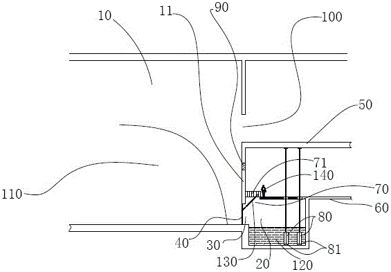
[0019] Such as figure 1 As shown, a leachate guiding device for an incineration plant garbage pool includes a garbage incineration tank 10 and a leachate collection tank 20 adjacent thereto. There is a vertical pool wall 11 adjacent to the garbage incineration tank 10 and the leachate collection tank 20; Above the leachate collection tank 20 is a garbage discharge platform 50, between the lower section of the vertical pool wall 11 and the bottom of the garbage incineration tank 10 is a leachate collection port 30 with a grid 40 installed; the height of the grid 40 is 2.5 ±0.5 meters, preferably 3 meters.

[0020] An operating platform 60 extending toward the vertical pool wall 11 is provided on the top of the leachate collection tank 20 and below the garbage discharge platform 50, but there is still a grid for observation between the operating platform 60 an...


PUM


Abstract

The invention discloses a guiding and draining device for leachate in an incineration plant rubbish pool. The guiding and draining device comprises a rubbish incineration pool (10) and a leachate collecting pool (20) adjacent to the rubbish incineration pool (10); and a vertical pool wall (11) is arranged at the adjoining position of the rubbish incineration pool (10) and the leachate collecting pool (20). A rubbish discharging platform (50) is arranged above the leachate collecting pool (20); and a leachate collecting opening (30) with gratings (40) is formed between the lower section of the vertical pool wall (11) and the pool bottom of the rubbish incineration pool (10). An operation platform (60) extending to the vertical pool wall (11) is arranged at the position, below the rubbish discharging platform (50), of the top of the leachate collecting pool (20), and a gap (70) used for allowing a user to observe whether the gratings (40) are blocked or not is still reserved between the operation platform (60) and the vertical pool wall (11). The guiding and draining device is simple in structure, safe, reliable and convenient to use.

Description

technical field [0001] The invention relates to a drainage structure of garbage treatment equipment, in particular to a leachate guiding device for a garbage pool leachate of a garbage incineration plant. Background technique [0002] The height of the grid at the leachate collection port of the garbage pool leachate guide and drainage device in the prior art waste incineration power plant is too low, and the leachate contains a large amount of sludge, which causes the grid to be blocked and the leachate cannot flow into the leachate collection pool. After the blockage, the staff can only go down to the garbage incineration tank to unclog it manually, and there is a lot of methane and other harmful gases deep in the garbage incineration tank, making maintenance very dangerous. Contents of the invention [0003] The technical problem to be solved by the present invention is to avoid the deficiencies of the above-mentioned prior art and provide a leachate guide and drainage...

Claims


Application Information

Patent Timeline
Patent Type & Authority Patents(China)
IPC IPC(8): E03F1/00E03F5/10E03F5/14
CPCE03F1/00E03F5/08E03F5/10
Inventor 张体强韦晓宁谢建张安平
Owner DYNAGREEN ENVIRONMENTAL PROTECTION GROUP
Learn More