Water flow speed increasing device for bulb tubular generator set

A speed-increasing device and generator set technology, which is applied in the direction of reaction engines, hydroelectric power generation, machines/engines, etc., can solve the problems of reduced flexibility, weak water flow guidance ability, and weak water flow speed-up ability, so as to avoid irregular impact , the structure is simple and reasonable, and the speed-up effect is remarkable

Inactive Publication Date: 2015-03-11
STATE GRID CORP OF CHINA +1
View PDF7 Cites 5 Cited by
  • Summary
  • Abstract
  • Description
  • Claims
  • Application Information

AI Technical Summary

Problems solved by technology

[0002] When using hydropower to generate electricity, the flow rate and direction of the water flow directly play a decisive role in the working efficiency and operating state of the generator, especially in the case of bulb tubular power generation This phenomenon is more obvious when the unit is generating electricity. In order to improve the power generation efficiency of the generator and the stable operation of the generator set, the current common practice is to install a water flow speed-up device at the front of the generator. However, in use, it is found that most of the water flow speed increasing devices currently used are trumpet-shaped structures, which are fixed in structure and do not have flexible adjustment capabilities, so their ability to guide water flow is relatively weak, and when adjusting water flow On the other hand, it can only operate at a fixed ratio without any adjustment capability, which greatly reduces the flexibility of its use, and ultimately leads to its weak water flow growth rate, which cannot effectively meet the needs of actual use.

Method used


Image

  • Water flow speed increasing device for bulb tubular generator set

Examples


Embodiment Construction

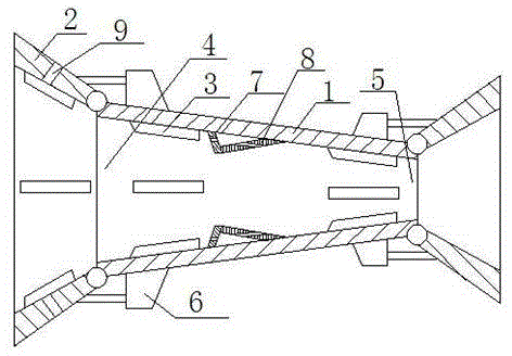
[0014] Compared with the traditional water flow speed-up equipment, the present invention has a simpler and more reasonable structure, and the speed-up effect is more significant. At the same time, it also has the functions of actively adjusting the speed-up and actively draining and diverting the water flow, so that on the one hand, it is convenient On the other hand, the water flow speeds up, and on the other hand, it also avoids irregular impacts on subsequent generator sets caused by turbulent flow, which helps to improve the stability of generator operation.

[0015] The basic principles and main features of the present invention and the advantages of the present invention have been shown and described above. Those skilled in the industry should understand that the present invention is not limited by the above-mentioned embodiments. What are described in the above-mentioned embodiments and the description only illustrate the principle of the present invention. Without depa...


PUM


Abstract

The invention relates to a water flow speed increasing device for a bulb tubular generator set. The device comprises a speed increasing tube, at least four drainage plates, a guide plate and at least four speed increasing plates. The speed increasing tube is in a hollow truncated pyramid structure, a water inlet is formed in the lower bottom, a water outlet is formed in the upper bottom, and the at least four drainage plates are arranged on the tube wall of the water inlet and the water outlet and are hinged to the tube wall of the speed increasing tube. An angle adjusting mechanism is further arranged, and the guide plate is disposed in the speed increasing tube and is perpendicular to the inner wall of the speed increasing tube and distributed along the axial direction of the speed increasing tube. The at least four speed increasing plates are connected with the inner wall of the speed increasing tube and are distributed in the same horizontal plane. Each of the speed increasing plates comprises a compression plate and a pressure relief plate. According to the device, functions of speed increasing active adjusting and active drainage and guide of water flows are provided, and accordingly, water flow speeding up is facilitated, irregular impact of turbulence and the like on subsequent generator sets is prevented, and the generator operation stability is improved.

Description

technical field [0001] The invention relates to a water flow speed-up device for a bulb tubular generator set, and belongs to the technical field of water level detection equipment for hydropower generation. Background technique [0002] When using hydropower to generate electricity, the flow velocity and direction of the water flow directly play a decisive role in the working efficiency and operating state of the generator, especially when the bulb tubular generator set generates electricity, this phenomenon is more obvious. In order to improve the generator The power generation efficiency and the stable operation of the generator set, the current common practice is to install a water flow speed-up device in front of the generator, and adjust the water flow velocity and flow direction through the speed-up device, but it is found in use that the current water flow speed-up Most of the speed devices are bell-shaped structures, fixed in structure, and do not have flexible adju...

Claims


Application Information

Patent Timeline
Patent Type & Authority Applications(China)
IPC IPC(8): F03B3/16F03B3/18
CPCF03B3/16F03B3/18Y02E10/20
Inventor 李江涛赵庆治王黎冬刘平陈鹏高天里郭夫然胡江雪张琨
Owner STATE GRID CORP OF CHINA
Why Eureka
Try Eureka