Power-assisted transmission structure for traveling machine

A technology for power-assisted transmission and machinery, which is applied in control devices, transportation and packaging, vehicle components, etc., can solve the problems of complex structure of power-assisted transmission, high energy consumption, low work efficiency, etc., to avoid energy consumption and resistance, reduce The effect of low energy consumption and improved work efficiency

Active Publication Date: 2018-07-06
ZHEJIANG SAFUN IND
View PDF27 Cites 0 Cited by
  • Summary
  • Abstract
  • Description
  • Claims
  • Application Information

AI Technical Summary

Problems solved by technology

[0003] The present invention provides a new power-assisted transmission structure for traveling machines, aiming at the defects of complex structure, high production cost, high energy consumption and low work efficiency in the prior art.

Method used


Image

  • Power-assisted transmission structure for traveling machine
  • Power-assisted transmission structure for traveling machine
  • Power-assisted transmission structure for traveling machine

Examples


Embodiment 1

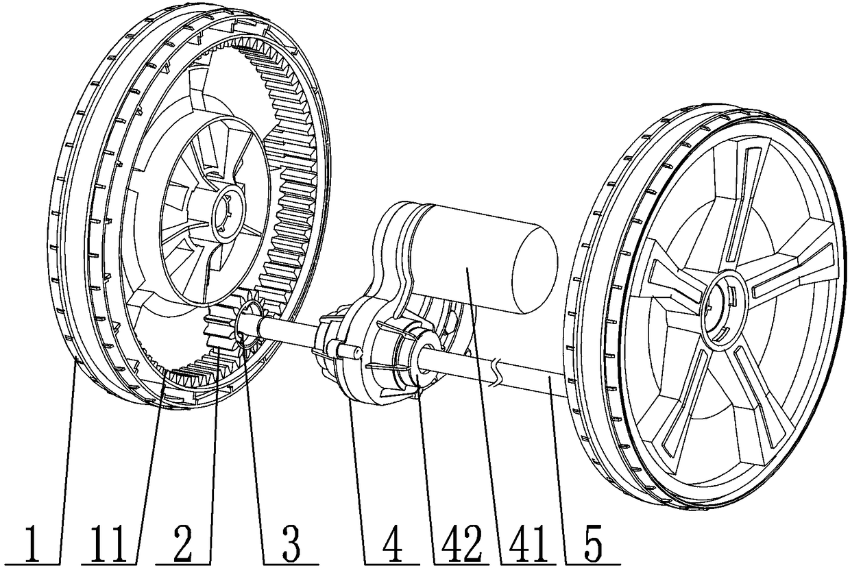
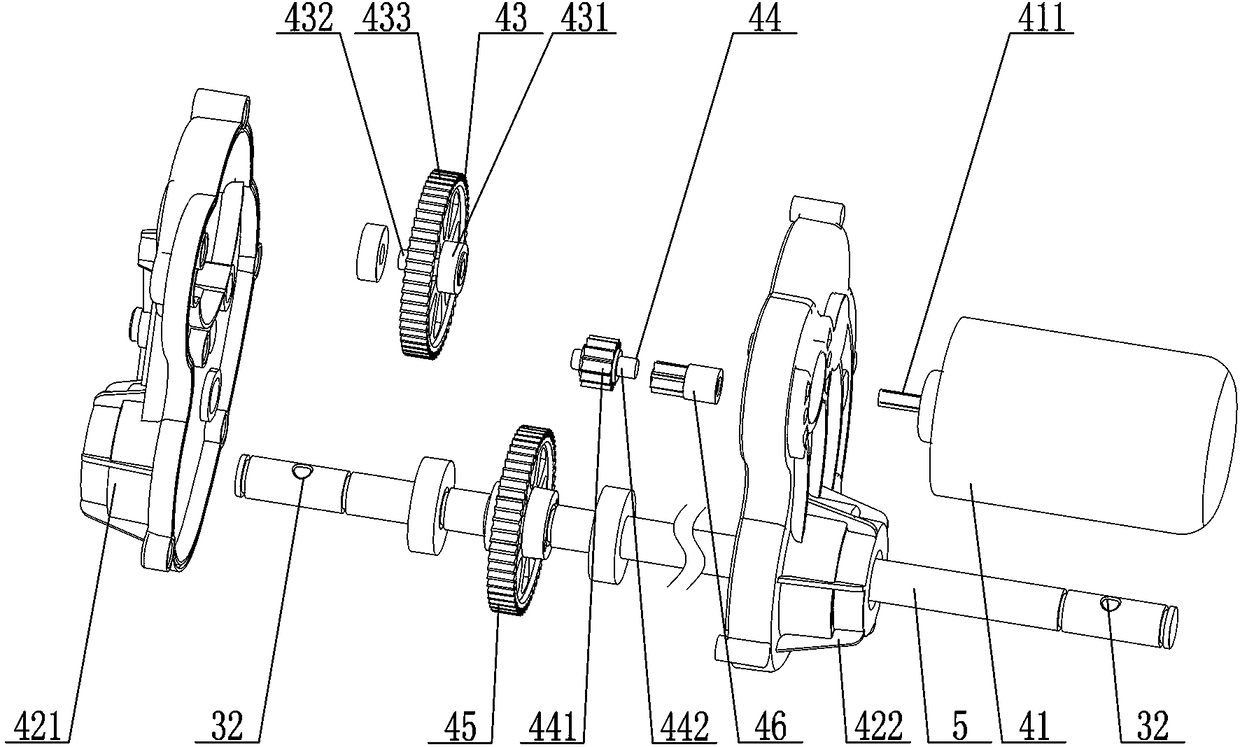
[0041] A power-assisted transmission structure of a traveling machine, comprising a power-assisted transmission device 4, a power-assisted output shaft 5, and a walking wheel 1, the power-assisted transmission device 4 provides driving assistance for the walking wheel 1 through the power-assisted output shaft 5, and the power-assisted transmission device The transmission device 4 includes a casing 42, a driving motor 41, and the driving motor 41 is connected to the casing 42. The power-assisted transmission device 4 also includes a driving gear assembly 43, an output gear 45, and a floating gear assembly 44. The driving gear The component 43 and the output gear 45 are respectively rotatably connected in the casing 42, the driving gear component 43 is driven by the driving motor 41, the output gear 45 is arranged on the power output shaft 5, and the floating gear component 44 meshes with the driving gear assembly 43, and a sliding track 47 is also provided in the casing 42. The ...

Embodiment 2

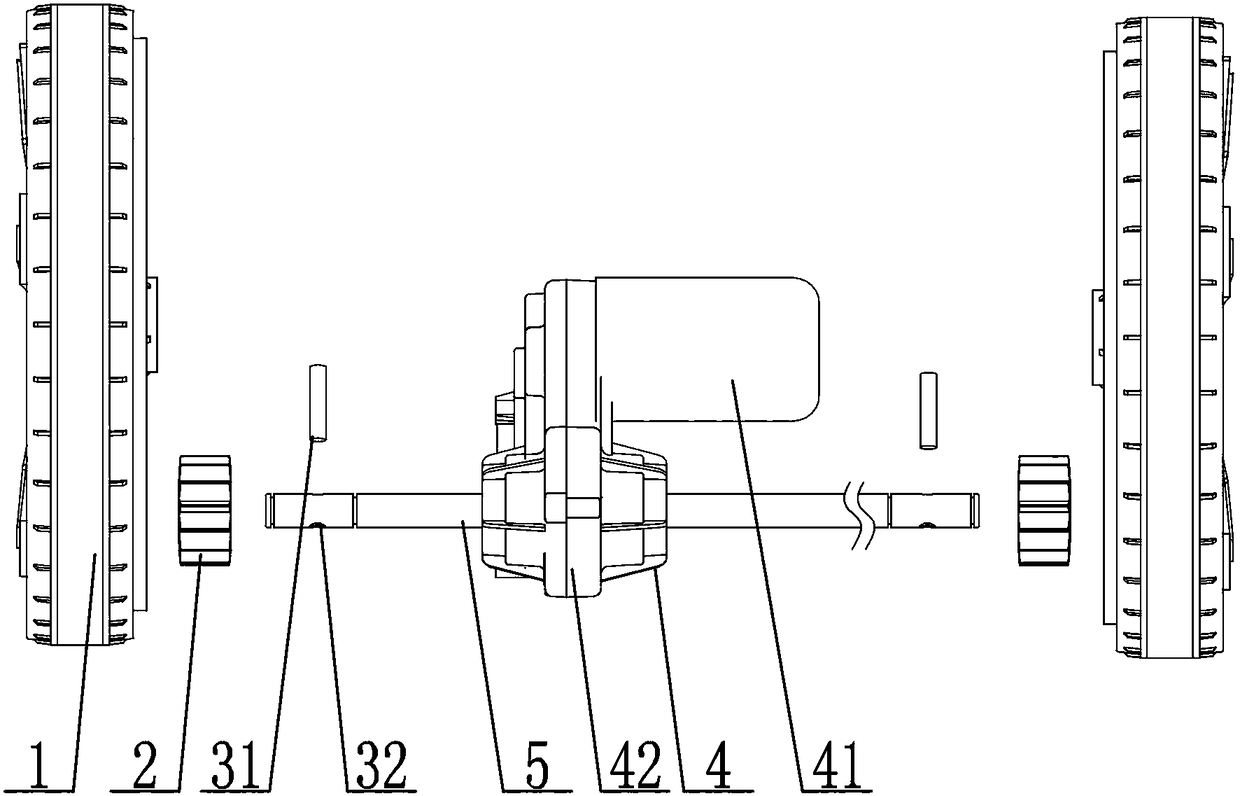
[0053] On the basis of Embodiment 1, as a preference, it also includes a one-way gear 2, and the inner side of the walking wheel 1 is also provided with a connecting tooth track 11, and the one-way gear 2 is connected to the connecting tooth track 11 of the walking wheel 1. meshing, a one-way drive structure 3 is provided between the one-way gear 2 and the booster output shaft 5, and the booster output shaft 5 drives the one-way gear 2 to rotate in one direction through the one-way drive structure 3 .

[0054] Preferably, the one-way driving structure 3 includes a transmission pin 31, a ratchet slideway 21, and a sliding through hole 32. In the one-way gear 2 , the transmission pin 31 is slidingly connected with the sliding through hole 32 and the end of the transmission pin 31 is matched with the ratchet slideway 21 in the one-way gear 2 .

[0055] Preferably, the length of the transmission pin 31 is smaller than the diameter of the ratchet top circle 22 of the ratchet slidew...


PUM


Abstract

The invention discloses a power-assisted transmission structure for a traveling machine. The power-assisted transmission structure comprises a power-assisted transmission device, a power-assisted output shaft and traveling wheels. The power-assisted transmission device comprises a shell, a driving motor, a driving gear component, an output gear and a float gear component, the driving motor is connected with the shell, the driving gear component drives through the driving motor, the output gear is arranged on the power-assisted output shaft, and the float gear component meshes with the drivinggear component. The shell is internally provided with a slide rail, the float gear component is in slide connection with the slide rail and provided with a mesh position formed by meshing with the output gear and a separation position formed by separation from the output gear. The power-assisted transmission structure has advantages that increasing of energy consumption and resistance in use due to the fact that the output gear drives the driving motor to rotate can be prevented, an internal structure of the power-assisted transmission device is simplified, risks of faults among parts and weight of the power-assisted transmission device are reduced, and accordingly operating energy consumption is reduced, and operating efficiency is improved.

Description

technical field [0001] The invention relates to a booster structure, in particular to a booster transmission structure of a traveling machine. Background technique [0002] Driving machines are widely used in gardening operations, such as brush cutters, grass combers, fertilizing vehicles, garden seeders, lawn mowers, lawn trimmers, etc. In the past, driving machines were driven by human operation, which is relatively It is laborious. In order to save manpower, a booster device was installed on the driving machine. The booster device is equipped with a power-assisted transmission structure. The structure of the existing power-assisted transmission structure is complex, resulting in high production costs, and will greatly increase the weight of the driving machine, thereby greatly increasing the energy consumption, which is not conducive to popularization and use, and the existing power-assisted transmission structure is prone to drag The reverse rotation of the output shaft...

Claims


Application Information

Patent Timeline
Patent Type & Authority Applications(China)
IPC IPC(8): B60K17/04
CPCB60K17/04
Inventor 孙亮亮应鑫森许海兵孙迎迎
Owner ZHEJIANG SAFUN IND
Why Eureka
Try Eureka