Method for establishing rolling blade die cavity

A technology for rolling blades and molds, which is applied in special data processing applications, instruments, electrical digital data processing, etc., and can solve problems such as poor cavity accuracy of rolling blade molds

Inactive Publication Date: 2015-03-11
NORTHWESTERN POLYTECHNICAL UNIV
View PDF1 Cites 10 Cited by
  • Summary
  • Abstract
  • Description
  • Claims
  • Application Information

AI Technical Summary

Problems solved by technology

[0004] In order to overcome the deficiency of the poor accuracy of the mold cavity of the rolling blade designed by the existing method, the present invention provides a method for establishing the mold cavity of the rolling blade

Method used


Image

  • Method for establishing rolling blade die cavity
  • Method for establishing rolling blade die cavity
  • Method for establishing rolling blade die cavity

Examples


Embodiment Construction

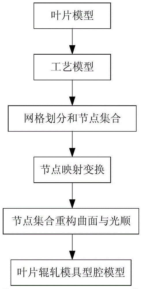
[0027] refer to Figure 1-3 . The present invention sets up the method concrete steps of rolling blade mold cavity as follows:

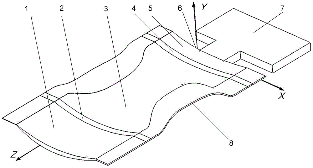
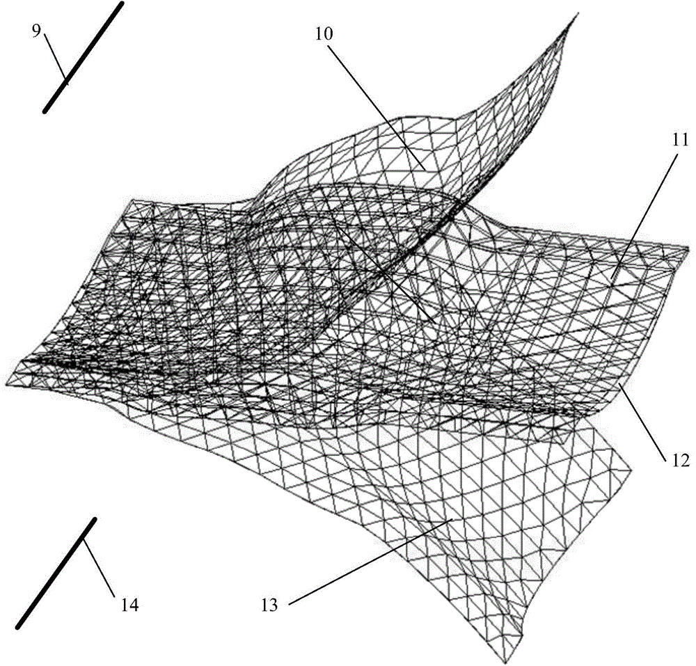
[0028] The present invention is described in detail by taking the establishment of the compressor blade rolling mold cavity model in UG NX7.0 software as an example.

[0029] Step 1: Start the UG NX7.0 modeling module, import the compressor blade model 3, and extend the blade tip along the opposite direction of the blade body to half the maximum diameter of the inscribed circle of the section line, which is Cmax / 2, to form the blade tip process transition 2, Build the leaf-root process transition4. Extract the tip section line of the blade tip process transition 2 and offset it 5 times in reverse along the blade body with a spacing of 2 mm, and establish a solid body through the offset section line group to form the blade tip process compensation 1. Extract the 4 root-end section lines of the blade root process transition and offset them three tim...


PUM


Abstract

The invention discloses a method for establishing a rolling blade die cavity, and aims to solve the technical problem of poor accuracy of a rolling blade die cavity designed through the conventional method. According to the technical scheme, the method comprises the following steps: establishing a rolling blade process model by designing front and back edge adding allowances, overflow edges, blade point and point root allowances and a process positioning reference for a blade; performing grid partitioning on the blade basin and blade back curved surfaces of the process model, extracting blade basin and blade back network nodes respectively to establish a point set, and coding; determining the radius of a rolling die, and performing wrapping mapping conversion on the blade basin and blade back curved surface point set to obtain a male die and female die cavity point set of a rolling die; establishing die cavity grids based on the grid node coding information of the process model, and performing smoothening optimization on the grids to obtain the die cavity curved surface of the rolling die. The die cavity of the rolling die is designed on the aspect of geometric transformation, automatic modeling of the rolling blade die cavity is realized, the current situation of designing of the rolling die by means of experience and die repair is changed, and the design accuracy of the rolling blade die cavity is increased.

Description

technical field [0001] The invention relates to a method for establishing a mold cavity of a rolling blade. Background technique [0002] Blade rolling precision forming technology is an advanced blade processing method. With its advantages of high production efficiency, high dimensional accuracy and good structure performance, it has become an important processing method for aero-engine high-pressure compressor blades. The die is a tool for roll forming, and the cavity of the rolling die is the most important factor affecting the accuracy of the rolling blade. The establishment of the rolling die cavity is based on the rolling process model, so the rationality of the rolling blade process modeling method is important. [0003] The document "Patent Publication No. CN 1887459A Chinese Invention Patent" discloses a method for manufacturing a blade with variable wall thickness and its roll forming device. and device. This method is aimed at the cross-rolling of non-twisted b...

Claims


Application Information

Patent Timeline
Patent Type & Authority Applications(China)
IPC IPC(8): G06F17/50
Inventor 汪文虎靳淇超赵德中解晓娜张艳熊一峰宋国栋林坤阳
Owner NORTHWESTERN POLYTECHNICAL UNIV
Why Eureka
Try Eureka