Containment Recirculation System

A recycling system and containment technology, applied in the field of nuclear technology safety equipment, can solve the problem of no filtration, and achieve the effects of reducing impact, reducing radioactivity, and reducing the release of fission products

Active Publication Date: 2017-07-04
NUCLEAR POWER INSTITUTE OF CHINA
View PDF12 Cites 0 Cited by
  • Summary
  • Abstract
  • Description
  • Claims
  • Application Information

AI Technical Summary

Problems solved by technology

[0006] Problem 1. Currently, in the severe accident management of power plants, the purpose of applying the containment filtration and discharge system for active containment discharge is limited to alleviating the threat of overpressure and hydrogen to the integrity of the containment. The reason is that the severe accident management guidelines for power plants (SAMG ) generally refers to the general guidelines of the Westinghouse Owners Group, and Westinghouse power plants generally do not have CFES design. emission;
[0007] The second problem is that according to the current design of CFES, the actively discharged containment gas is discharged to the atmosphere after the containment filtration and discharge system, resulting in the release of radioactivity, which makes the system highly questionable at present

Method used


Image

  • Containment Recirculation System
  • Containment Recirculation System
  • Containment Recirculation System

Examples


Embodiment 1

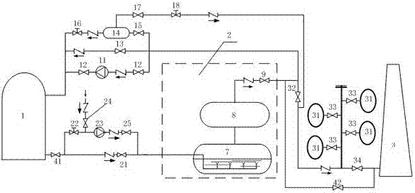
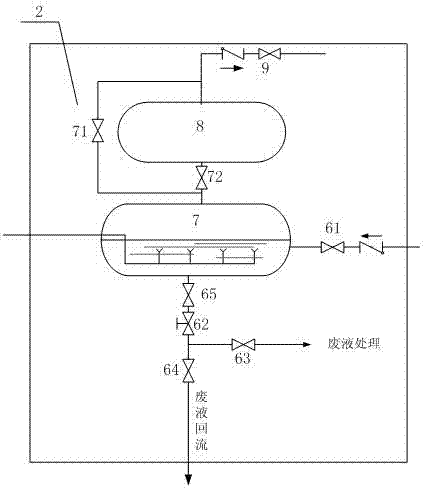
[0037] like figure 1 As shown, the containment recirculation system includes a containment vessel 1, a containment filtration and discharge system 2 (CFS), an air discharge mechanism 3 connected in sequence, and an air discharge mechanism 3 for the temporary storage of the containment filtration and discharge system 2. The retention pipeline of the gas, used to return the gas discharged from the outlet of the containment filter discharge system 2 or the gas temporarily stored on the retention pipeline to the return line of the containment vessel 1, used to discharge the gas in the containment vessel 1 to the containment vessel Pressure relief line for filter discharge system 2.

[0038] The upstream of the return pipeline is connected to the outlet of the containment filtration and discharge system 2, and the downstream is connected to the inner space of the containment vessel 1; the upstream of the retention pipeline is connected to the outlet of the containment filtration an...

Embodiment 2

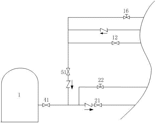
[0043] On the basis of Embodiment 1, this embodiment further explains the return pipeline:

[0044] The return pipeline includes three parallel pipelines, the first pipeline is provided with a return fan 11 and two control valves A12, the return fan 11 is arranged between the two control valves A12; the second pipeline is provided with a third isolation valve 13. The third pipeline is provided with a control valve K15, a pressure buffer tank 14, and a second flow regulating valve 16 in sequence. The control valve K15 is connected to the outlet of the containment filtration and discharge system 2. Spatial connectivity.

[0045] The containment vessel 1 can be actively discharged through the pressure relief pipeline to alleviate the threat of containment overpressure and hydrogen, and maintain the integrity of the containment vessel 1. The main purpose of setting the return pipeline in this embodiment is to filter the discharged gas from the containment filter and discharge syst...

Embodiment 3

[0055] On the basis of Embodiment 1, the pressure relief pipeline is further improved in this embodiment:

[0056] The pressure relief pipeline includes two parallel pipelines and a minimum flow pipeline; the two parallel pipelines are active and passive pressure relief pipelines respectively, the upstream of the two parallel pipelines are connected downstream of the first isolation valve 41, and the downstream is connected to the The inlet of the filter discharge system 2 is connected; one of the pipelines (passive pressure relief pipeline) is provided with a control valve B21, and the other pipeline (active pressure relief pipeline) is sequentially provided with a first flow regulating valve 22 along the direction of gas flow , exhaust fan 23, control valve C25, the exhaust fan 23 is located between the first flow regulating valve 22 and the control valve C25; the minimum flow pipeline is connected after the first flow regulating valve 22, and the minimum flow pipeline is pro...


PUM


Abstract

The invention relates to the technical field of nuclear equipment safety, and discloses a containment recirculation system, which includes a containment vessel connected in sequence, a containment filter discharge system, an air discharge mechanism, and a device for temporarily storing discharge gas from the outlet of the containment filter discharge system The retention pipeline, the return pipeline used to return the gas discharged from the outlet of the containment filter and discharge system or the gas temporarily stored in the containment to the containment, the pressure relief pipeline used to pump and discharge the gas in the containment to the containment filter and discharge system . The present invention can not only alleviate the threat of overpressure and hydrogen in the containment vessel and maintain the integrity of the containment vessel under serious accident conditions, but also alleviate the release of fission products and reduce the radioactivity of exhaust gas; in the prevention and mitigation stage of serious accidents , can condense water vapor to realize the function of the containment heat sink, can effectively perform the decompression of the containment at a specified rate, accurately maintain the containment pressure at a given target value, and maintain a small negative pressure in the containment.

Description

technical field [0001] The invention relates to the technical field of nuclear technology safety equipment, in particular to a containment recirculation system. Background technique [0002] According to the nuclear power safety concept of defense in depth and multiple barriers, the containment is the last barrier to prevent the release of radioactive fission products. When a serious accident occurs after the core is damaged, radioactive fission products are released into the containment, and the failure or leakage of the containment will cause the release of fission products to the environment. [0003] The large dry containment vessel of PWR is a pressurized structure, which allows a certain degree of normal leakage. During normal operation, the containment atmosphere control system maintains a small negative pressure in the atmosphere inside the containment, and no leakage to the environment occurs. In the accident analysis, it is usually assumed that the containment is...

Claims


Application Information

Patent Timeline
Patent Type & Authority Patents(China)
IPC IPC(8): G21C13/02G21C9/004G21F9/02
CPCG21C9/004G21C13/02G21F9/02Y02E30/30
Inventor 孔翔程关仲华邓坚邓纯锐张明张渝余红星
Owner NUCLEAR POWER INSTITUTE OF CHINA
Why Eureka
Try Eureka