Pushrod assembly for a medium voltage vacuum circuit breaker

A vacuum circuit breaker and push rod technology, which is applied to high-voltage air circuit breakers, circuits, electrical components, etc., can solve the problem that the minimum size of push rod components cannot be reduced any more

Inactive Publication Date: 2015-03-11
ABB TECH AG
View PDF6 Cites 0 Cited by
  • Summary
  • Abstract
  • Description
  • Claims
  • Application Information

AI Technical Summary

Problems solved by technology

However, due to this minimum distance, the minimum size of the pushrod assembly may not be reduced any further

Method used


Image

  • Pushrod assembly for a medium voltage vacuum circuit breaker
  • Pushrod assembly for a medium voltage vacuum circuit breaker
  • Pushrod assembly for a medium voltage vacuum circuit breaker

Examples


Embodiment Construction

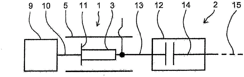
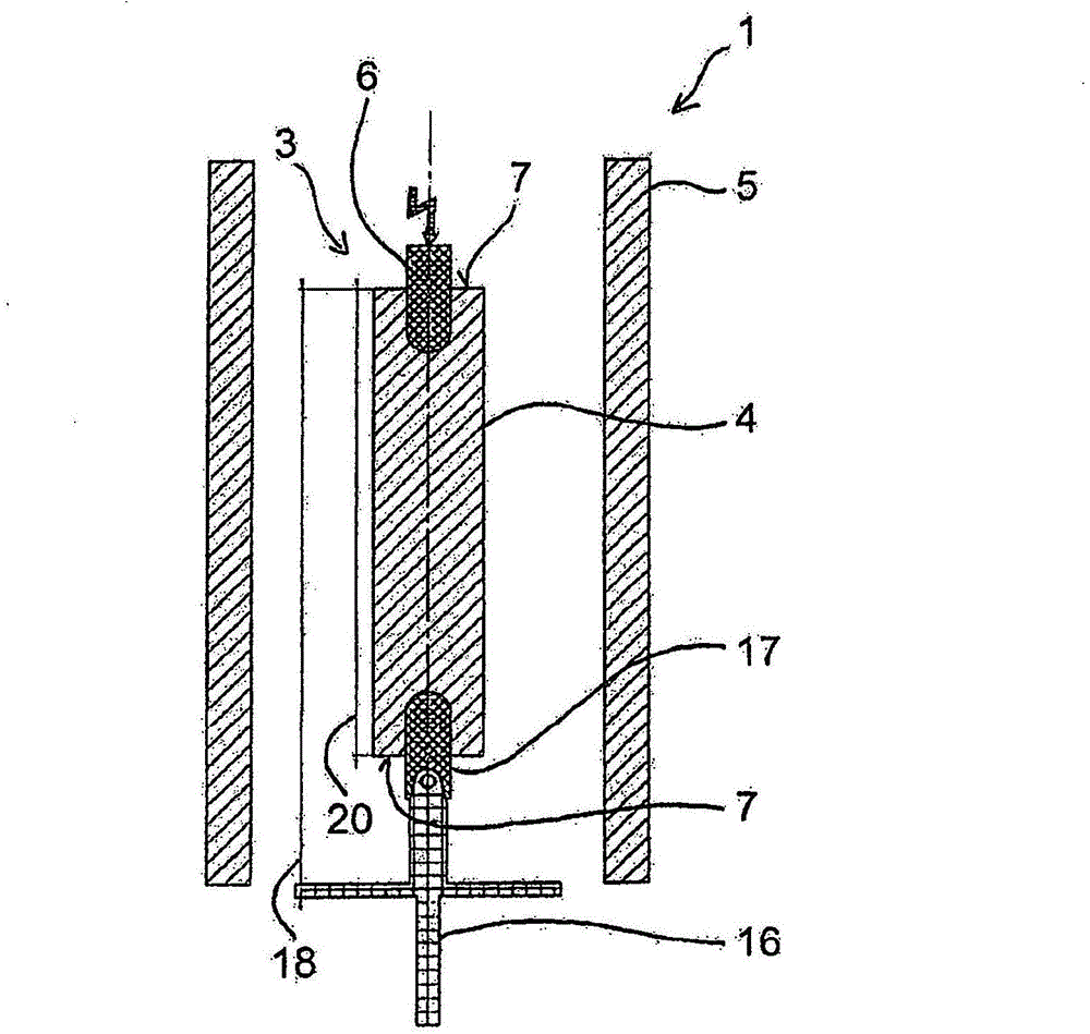
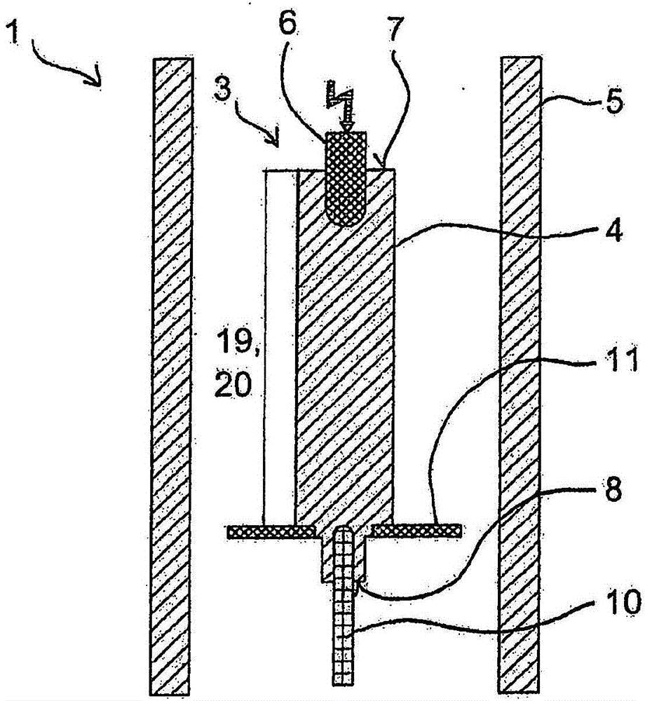
[0025] Such as figure 1 As shown in , the medium voltage vacuum circuit breaker 2 according to the embodiment of the present invention mainly includes a push rod assembly 1, which is mechanically connected with the electromagnetic actuator 9 on one side and connected with the vacuum switch chamber 12 on the other side. mechanical connection. The connection between the push rod assembly 1 and the electromagnetic actuator 9 is realized through a guide pin 10 . The guide pin 10 mechanically connects the push rod 3 of the push rod assembly 1 with the electromagnetic actuator 9 . The push rod 3 is surrounded by an insulating housing 5 which can also surround a switching chamber 12 . The connection between the push rod assembly 1 and the vacuum switch chamber is realized through the movable conductive terminal 13 . The push rod 3 can move along the axis 15 so as to connect and disconnect the movable conductive terminal 13 from the non-movable conductive terminal 14 .

[0026] Ac...


PUM


Abstract

The invention relates to a pushrod assembly (1) for a medium voltage vacuum circuit breaker (2), comprising a pushrod (3) with an insulating body (4), whereby an electrical conducting terminal (6) is arranged on a first abutting face (7) of the insulating body (4) and a guiding means is arranged on an opposing side of the electrical conducting terminal (6) on a second abutting face (8) of the insulating body (4) for mechanically connecting the pushrod (3) with an electromagnetic actuator (9), whereby the pushrod (3) is integrated in the electromagnetic actuator (9) and thus part of the electromagnetic actuator (9).

Description

technical field [0001] The invention relates to a push rod assembly for a medium-voltage vacuum circuit breaker, which includes a push rod with an insulating body and an insulating housing surrounding the push rod, wherein the conductive terminal is arranged on the first abutting surface of the insulating body The guiding device is arranged on the second abutting surface of the insulating body on the opposite side of the conductive terminal, for mechanically connecting the push rod with the electromagnetic actuator. [0002] Furthermore, the invention relates to a circuit breaker arrangement for medium voltage applications comprising at least one such push rod assembly. Background technique [0003] A circuit breaker may include two conductive terminals that are pushed against each other for making electrical contact and away from each other for breaking electrical contact. Thus, typically a circuit breaker includes an actuator mechanically interconnected to a push rod havi...

Claims


Application Information

Patent Timeline
Patent Type & Authority Applications(China)
IPC IPC(8): H01H33/666
CPCH01H33/6662H01H2033/6667H01H33/666H01H2221/024
Inventor C·罗伊贝尔P·马斯迈尔
Owner ABB TECH AG
Why Eureka
Try Eureka