A pressurized plane flame combustion device

A technology of plane flame and combustion device, which is applied in the field of plane flame combustion device and pressurized plane flame combustion device, which can solve the problems of low heating temperature, gap, slow heating rate, etc., and achieve the effect of high combustion rate

Active Publication Date: 2020-09-08
HUAZHONG UNIV OF SCI & TECH
View PDF5 Cites 0 Cited by
  • Summary
  • Abstract
  • Description
  • Claims
  • Application Information

AI Technical Summary

Problems solved by technology

[0003] There are many different types of pressurized heating systems, such as pressurized thermogravimetric analyzers, pressurized drop tube furnaces, pressurized fixed beds, pressurized flat flame furnaces, etc., but these systems have limitations: pressurized heat Heavy can only study the combustion of particles in a static state, and the heating temperature is low (generally lower than 1273K), and the heating rate is slow (3-200K / min); the pressurized dropper furnace can reach a high temperature and high pressure environment, but its heating rate is the highest It can only reach 103-104K / s; the pressurized fixed bed reactants are mostly large particles or accumulated powder layers, and the temperature is generally between 723-1273K, which is far from the actual application

Method used


Image

  • A pressurized plane flame combustion device
  • A pressurized plane flame combustion device
  • A pressurized plane flame combustion device

Examples


Embodiment Construction

[0031] In order to make the object, technical solution and advantages of the present invention clearer, the present invention will be further described in detail below in conjunction with the accompanying drawings and embodiments. It should be understood that the specific embodiments described here are only used to explain the present invention, not to limit the present invention. In addition, the technical features involved in the various embodiments of the present invention described below can be combined with each other as long as they do not constitute a conflict with each other.

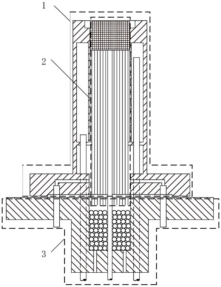
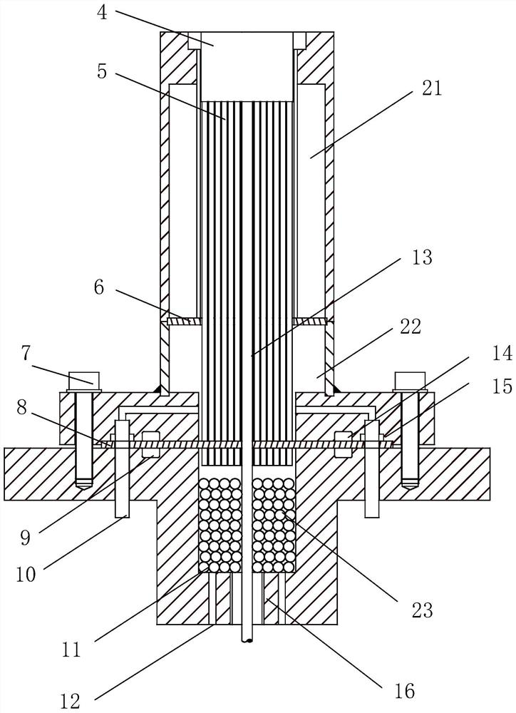
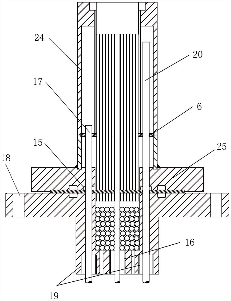
[0032] as attached Figure 1~5 As shown, a pressurized planar flame combustion device according to a preferred embodiment of the present invention is composed of a burner body 1 , a planar flame capillary inner core 2 and a base 3 .

[0033] The burner body 1 is provided with an inner core installation chamber and an oxidation gas chamber 22 , the upper end of the inner core installation chambe...


PUM


Abstract

The invention belongs to the field of research of reaction dynamics characteristics such as ignition, combustion and gasification of solid fuel particles, and discloses a pressurized plane flame combustion device. A combustor main body of the device is provided with an oxidizing gas cavity and a water cooling cavity; the upper end of the oxidizing gas cavity is opened, and an inner core is arranged in the center of the oxidizing gas cavity; an independent isolated cooling cavity is arranged in the side wall of the oxidizing gas cavity; a base comprises a fuel gas cavity, the fuel gas cavity islocated below the oxidizing gas cavity, and a sealing plate isolates the oxidizing gas cavity form the fuel gas cavity; and a planar flame capillary inner core comprises a honeycomb ceramic block, acapillary array and powder feeding tube. According to the pressurized plane flame combustion device, oxidation gas and fuel gas are transmitted and rectified separately, and finally a stable non-premixed plane flame is formed on the top surface of the honeycomb ceramic block to form a high-temperature and high-heating-rate flue gas environment is formed; and the hot-pressing deformation and heat failure are prevented through water cooling, and the sealing plate is matched with O-shaped rings for sealing, so that the pressurized plane flame combustion device can stably work in a high-temperature and high-pressure environment for a long time.

Description

technical field [0001] The invention belongs to the research field of reaction kinetic characteristics of discrete solid fuel particles such as ignition, combustion, and gasification, and relates to a pressurized planar flame combustion device, and more specifically, to a tissue controllable high temperature and high pressure device suitable for optical measurement Ambient flat flame combustion device. Background technique [0002] The reaction kinetic characteristics of micron and nanometer powder fuels such as ignition, combustion and gasification have important reference significance for the design of combustion devices. In practical applications, the powder reaction is often in a relatively extreme high temperature and high pressure environment, and has an extremely high heating rate in the actual combustion environment. Most laboratory equipment is difficult to meet such requirements. Therefore, a combustion system that can provide a high temperature and high pressure ...

Claims


Application Information

Patent Timeline
Patent Type & Authority Patents(China)
IPC IPC(8): F23D14/00F23D14/46F28D20/00F16J15/06F25D1/02
CPCF16J15/06F23D14/00F23D14/46F25D1/02F28D20/0056Y02E60/14
Inventor 王昱升栗晶陈前云柳朝晖张泰
Owner HUAZHONG UNIV OF SCI & TECH
Why Eureka
Try Eureka