A network node and a method therein for controlling uplink power control
A network node, power control technology, applied in power management, advanced technology, electrical components, etc., can solve the problems of increased battery waste, interference, etc., and achieve the effect of increasing system capacity, reducing interference level, and reducing battery consumption
- Summary
- Abstract
- Description
- Claims
- Application Information
AI Technical Summary
Problems solved by technology
Method used
Image

Examples
Embodiment Construction
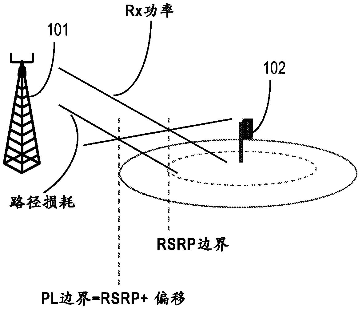
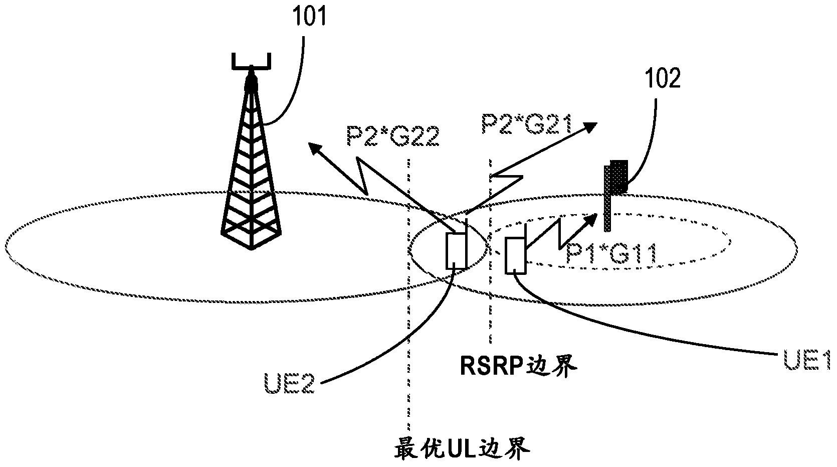
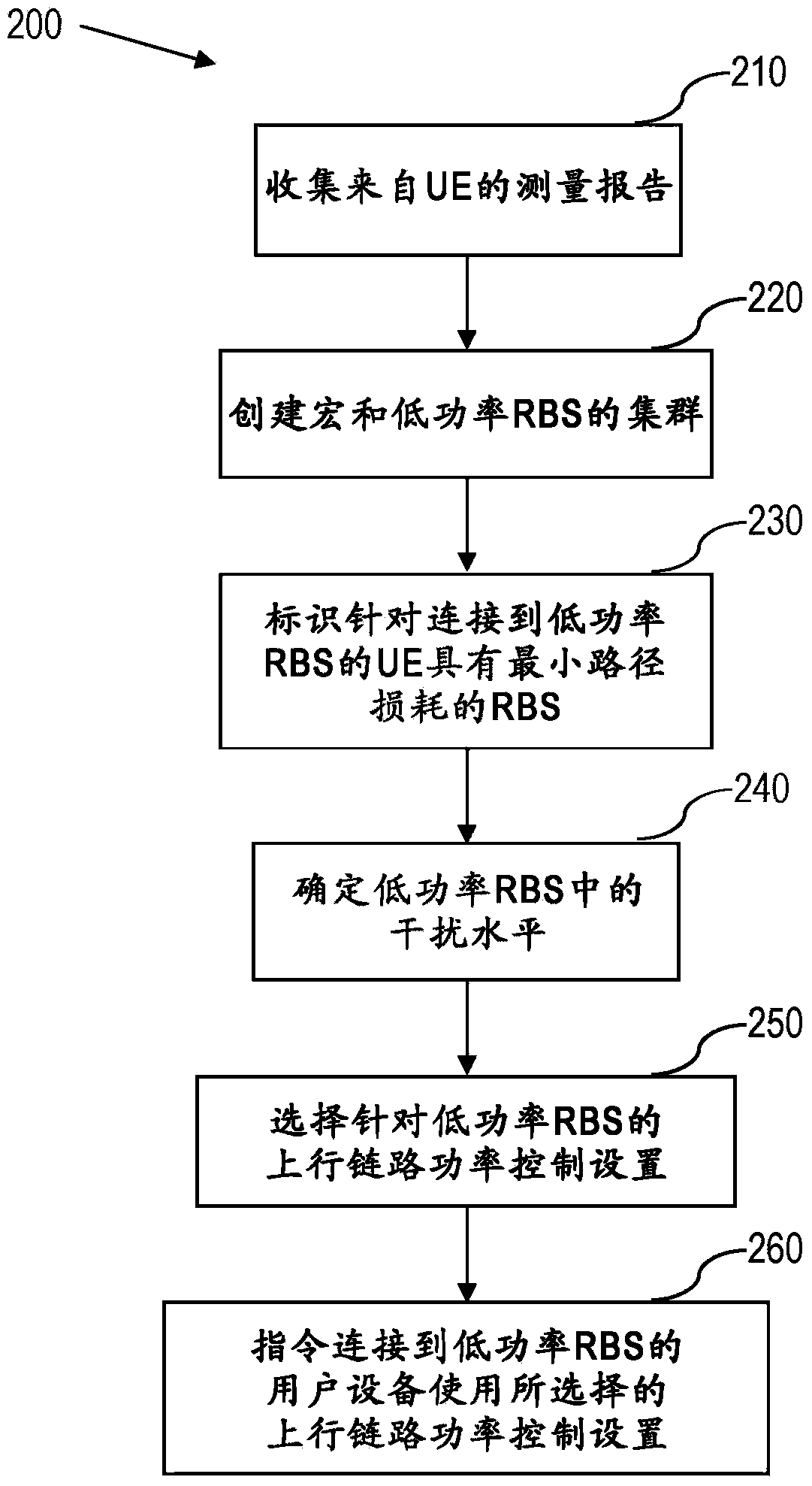
[0026]Briefly, exemplary embodiments of a network node and a method therein for controlling uplink power control within an area comprising at least one macro radio base station RBS and at least one low power RBS are provided. Briefly, a cluster of low power RBSs and macro RBSs is created based on measurement reports collected from UEs; the level of path loss is identified, and the level of interference in the low power RBSs is determined. Based on this, uplink power control settings are selected for low power RBSs.
[0027] will now refer to figure 2 To describe an exemplary embodiment of a method in a network node in a wireless communication network for controlling uplink power control in an area comprising at least one macro RBS and at least one low power RBS, figure 2 is a flowchart of a method for controlling uplink power control in a network node in a wireless communication network according to an exemplary embodiment.
[0028] figure 2 A method comprising collectin...
PUM
 Abstract
Description
Claims
Application Information
 - Generate Ideas
- Intellectual Property
- Life Sciences
- Materials
- Tech Scout
- Unparalleled Data Quality
- Higher Quality Content
- 60% Fewer Hallucinations
Browse by: Latest US Patents, China's latest patents, Technical Efficacy Thesaurus, Application Domain, Technology Topic, Popular Technical Reports.
© 2025 PatSnap. All rights reserved.Legal|Privacy policy|Modern Slavery Act Transparency Statement|Sitemap|About US| Contact US: help@patsnap.com