Food processing grinder

A food processing and pulverizer technology, applied in the field of kitchen utensils, can solve the problems of slag accumulation, reduce the service life of the motor, increase the temperature of the motor, etc., and achieve the effects of reducing vibration, reducing noise, and increasing lifespan

Inactive Publication Date: 2015-03-18
HARBIN XINHONGJU FOOD SCI & TECH
0 Cites 3 Cited by

AI-Extracted Technical Summary

Problems solved by technology

[0003] Yet, in the soya-bean milk machine of prior art, the pulverizer knife bar is longer, and when pulverizing device carries out pulverizing work to pulping material, the pinch of pulverizer knife bar The movement is relatively large, resulting in greater vibration of the who...

Method used

By motor 11 being arranged in the inner concave portion 121 of processing container 12, under the premise of not affecting the food production effect, motor sinks and is arranged on inner concave portion, thereby the length of pulverizer cutter bar can be shortened ...

Abstract

The invention relates to a food processing grinder. The food processing grinder comprises a motor, a grinding knife holder, a grinding knife and a processing vessel, the grinding knife holder enters the processing vessel, a motor drives the grinding knife to rotate, the processing vessel comprises a concave part which is formed through hollowing towards the grinding knife holder from the wall of the processing vessel, the concave part enters size, and the motor is firmly arranged on the concave part. Compared with the prior art, the motor of the food processing grinder is embedded in the concave part, the grinding knife holder is relatively shortened, the shortening of the grinding knife holder can reduce the jump of the grinding knife holder, and accordingly the noise is reduced, the vibration of the machine is lowered, and the life span of the motor can be increased.

Application Domain

Kitchen equipment

Technology Topic

Electric machineryEngineering +4

Image

  • Food processing grinder

Examples

  • Experimental program(1)

Example Embodiment

[0018] The present invention will be further described in detail below in conjunction with the drawings and embodiments:
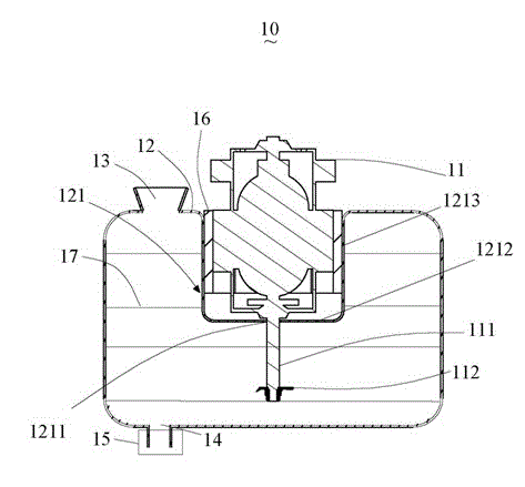
[0019] figure 1 The illustrated embodiment of the invention.
[0020] Such as figure 1 As shown, the food processing pulverizer 10 includes a motor 11, a pulverizing knife bar 111, a pulverizing knife 112, a processing container 12, an inner recess 121, a feed port 13, a pulp port 14, a valve 15, and a heat transfer medium 16. .
[0021] The motor 11 includes a crushing knife bar 111 and a crushing knife 112, and the crushing knife 112 is arranged at the end of the crushing knife bar 111. The motor 11 drives the crushing knife 112 to crush the pulping materials.
[0022] The processing container 12 is recessed to form an inner recess 121 which further includes a bottom wall 1212 and a side wall 1213. The bottom wall of the inner recess 121 penetrates through a shaft hole 1211 for the pulverizing knife rod to pass through. The motor 11 of the pulverizing device is fixedly installed on the inner recess 121, the pulverizing knife rod 111 passes through the shaft hole 1211 of the inner recess 121 and extends into the processing container 12, and the pulverizing knife 112 is installed at the end of the pulverizing knife rod 111 and extends Among the pulping materials in the processing container 12, the motor 11 drives the pulverizing knife 112 to rotate to cut and pulverize the pulping materials in the processing container 12 to form a slurry 17. In this embodiment, the inner recess 121 is provided on the upper part of the processing container 12, so that the motor 11 is placed on the processing container.
[0023] The feed inlet 13 is arranged at the upper part of the processing container 12 and is used to put materials into the processing container 12. The slurry outlet 14 is provided in the lower part of the processing container 12 for the prepared slurry 17 to flow out. The valve 15 is arranged on the slurry outlet 14 for controlling the slurry 17 to flow out of the slurry outlet 14.
[0024] The heat-conducting medium 16 is disposed in the cavity formed between the side wall 1213 of the inner recess 121 and the motor 11, and the heat-conducting medium 16 is used to transfer the heat generated by the motor 11 during the crushing operation to the liquid in the processing container 12. When making food, first, the materials and water waiting to be made are put into the processing container 12 from the feed port 13, and then the crushing knife 112 is driven by the motor 11 to rotate, so that the pulping materials in the processing container 12 are cut and crushed. The slurry 17 is produced. The heat generated by the motor 11 during the crushing work is transferred by the heat transfer medium 16. The heat is transferred to the slurry 17 in the processing vessel 12, and then the heating device (not shown) affects the processing vessel 12 The slurry 17 is cooked and heated until the slurry is cooked, and finally controlled by the valve 15, the slurry 17 flows out from the slurry outlet 14, thus completing the entire slurry process.
[0025] By arranging the motor 11 in the inner recess 121 of the processing container 12, the motor is sunk and arranged in the inner recess without affecting the food production effect, so that the length of the pulverizing blade can be relatively shortened, and the length of the pulverizing blade can be relatively shortened. The shortening can reduce the movement of the crushing knife and the knife bar, so it can reduce the vibration of the entire machine, reduce the noise generated by the machine, and extend the service life of the motor.
[0026] In this embodiment, the fixing method of the motor can be a general fixing method such as screw fixing. Such insubstantial changes that are not in the present invention are also within the protection scope of the present invention, and will not be exemplified here.

PUM

no PUM

Description & Claims & Application Information

We can also present the details of the Description, Claims and Application information to help users get a comprehensive understanding of the technical details of the patent, such as background art, summary of invention, brief description of drawings, description of embodiments, and other original content. On the other hand, users can also determine the specific scope of protection of the technology through the list of claims; as well as understand the changes in the life cycle of the technology with the presentation of the patent timeline. Login to view more.

Similar technology patents

Emission control apparatus

InactiveUS20020106312A1reduce gas emissionreduce noise
Owner:CLEAN AIR POWER

Flexible liner air gap pipe

InactiveUS20050011573A1reduce noise
Owner:AMERICAN BOA

Classification and recommendation of technical efficacy words

  • reduce vibration
  • reduce noise

Fracturing manifold quick connecting device

Owner:YANTAI JEREH PETROLEUM EQUIP & TECH

Startup control method of brushless DC motor

InactiveUS20060132075A1reduce vibrationcurrent be restrict
Owner:SAMSUNG ELECTRONICS CO LTD

Integrated quiet Motorized Roller Shade System

InactiveUS20100307701A1reduce vibrationreduce transmission of sound
Owner:PETERSON THOMAS

Liver subsection method based on CT image and system thereof

InactiveCN101425186Areduce noiseavoid blur
Owner:HUAZHONG UNIV OF SCI & TECH

Noise reduction device

ActiveUS20100014683A1reduce noisehigh quality
Owner:PANASONIC CORP

Automatic image capture

ActiveUS20110170740A1reduce noiseenhance edge
Owner:NORTHWEST IP LLC +1
Why Eureka
Try Eureka