Catalyst regeneration method and regenerator

A regenerator and catalyst technology, which is applied in petrochemical and fluidization fields, can solve the problems of long burning time of catalyst, high activity of regenerant, low activity of regenerant, etc., achieve consistent burning time and increase the ratio of agent to oil in the device , Consistent effect of regenerant activity

Inactive Publication Date: 2015-03-18
刘英聚
View PDF0 Cites 3 Cited by
  • Summary
  • Abstract
  • Description
  • Claims
  • Application Information

AI Technical Summary

Problems solved by technology

This way of entry and exit leads to inhomogeneity of the spent agent in the coking process of the fluidized bed
This unevenness leads to the following problems: some catalysts burn for a long time, the carbon content of the regenerant is low, and the activity of the regenerant is high; while some catalysts burn for a short time, the carbon content of the regenerant is high, and the activity of the regenerant is low

Method used


Image

  • Catalyst regeneration method and regenerator
  • Catalyst regeneration method and regenerator
  • Catalyst regeneration method and regenerator

Examples


Embodiment Construction

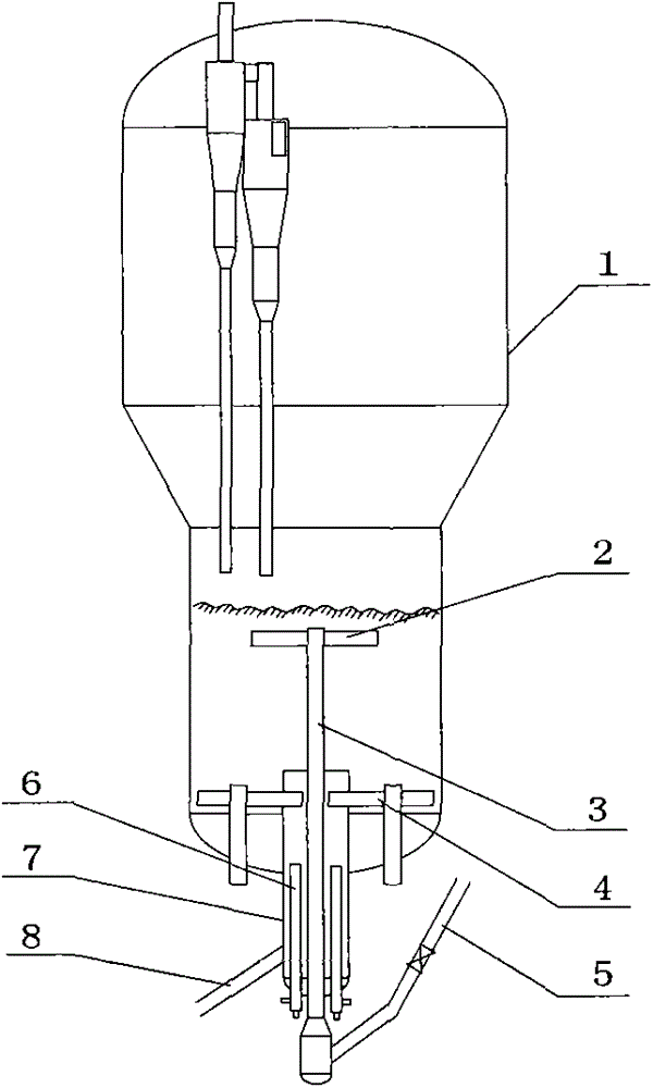
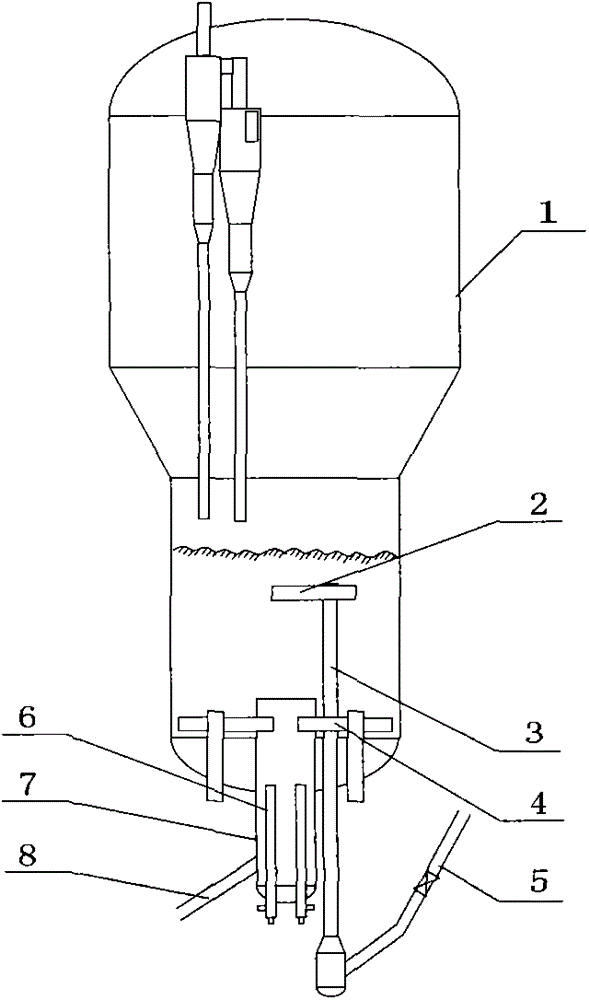
[0020] See figure 1 , figure 2 , the lower part of the regenerator 1 has the main air distribution pipe 4, and the central lead-out pipe 7 extends from the bottom center of the regenerator 1 from bottom to top, and its lower part is connected with the regenerant delivery pipe 8, and the heat-taking pipe 6 extends into the central lead-out pipe 7 from bottom to top . The spent agent riser 3 extends into the regenerator 1 through the central outlet pipe 7 from bottom to top, its upper end is connected with the spent agent distributor 2 , and its lower end is connected with the spent agent feed pipe 5 . figure 2 The spent agent riser 3 directly extends into the regenerator 1.

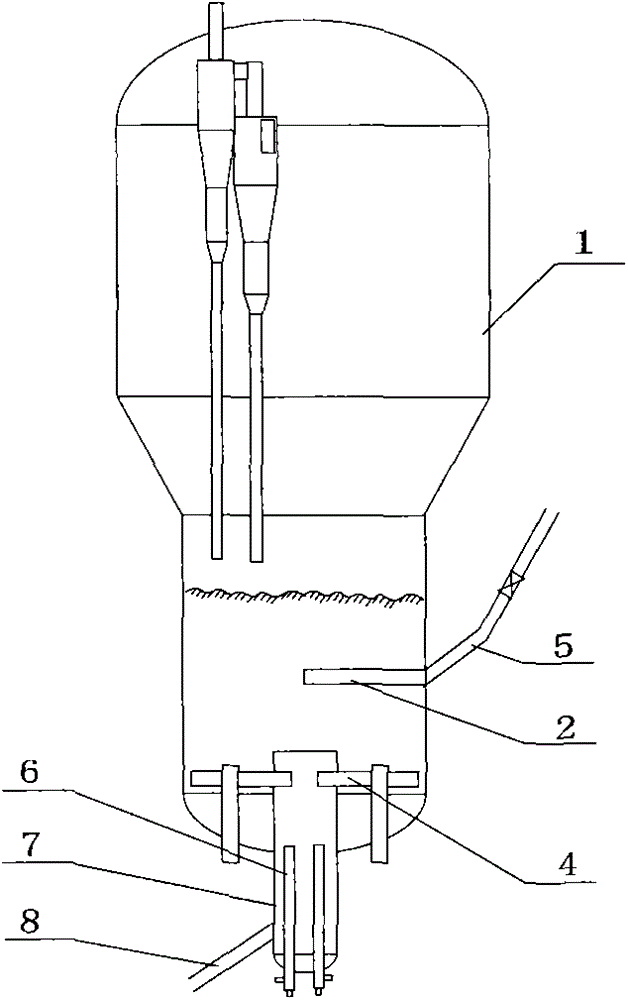
[0021] See image 3 , the lower part of the regenerator 1 has the main air distribution pipe 4, and the central lead-out pipe 7 extends from the bottom center of the regenerator 1 from bottom to top, and its lower part is connected with the regenerant delivery pipe 8, and the heat-taking pipe 6 extend...


PUM


Abstract

The invention provides a catalyst regeneration method, belonging to the technical field of petrochemical engineering and fluidization and aiming to improve the burning efficiency of a fluidized bed regenerator. The catalyst regeneration method comprises spent catalyst feeding, main air feeding, fluidized bed burning and regenerating agent discharging, and is characterized in that a turbulent flow bed is in reverse contact to be burnt; a spent catalyst passes through the distributor to enter from the upper part of a fluidized bed and is distributed; a regenerating agent is led out from the central position of the lower part of the fluidized bed; and heating is set so that the temperature of the regenerating agent is lowered and the agent-oil ratio of the device is improved. According to the method, the burning time of the spent catalyst in the fluidized bed can be consistent, the carbon content of the regenerating agent is consistent, the activity of the regenerating agent is consistent, the temperature of the regenerating agent is lowered and the agent-oil ratio of the device is improved. The invention further provides regenerator which can be used for realizing the method and is composed of a central leading-out pipe, a regenerating agent conveying pipe, a spent catalyst feeding pipe and a spent catalyst lifting pipe. The catalyst regeneration method is applied to catalytic cracking and methanol-to-olefin device regenerators.

Description

technical field [0001] The invention belongs to the technical fields of petrochemical industry and fluidization, and in particular relates to a catalyst regeneration method and a regenerator. Background technique [0002] In the existing parallel catalytic cracking unit, the spent agent enters the fluidized bed from the side, and most of the units do not have a spent agent distributor (a few units have simple distributors), and the regenerated agent is supplied from the side of the regenerator or from a certain quadrant in the lower part lead out. This way of entry and exit leads to inhomogeneity of the spent agent in the coking process of the fluidized bed. This unevenness leads to the following problems: some catalysts burn for a long time, the regenerant has low carbon content, and the regenerant activity is high; while some catalysts burn for a short time, the regenerant has high carbon content, and the regenerant activity is low . When the above-mentioned catalyst en...

Claims


Application Information

Patent Timeline
Patent Type & Authority Applications(China)
IPC IPC(8): B01J38/30
Inventor 刘英聚
Owner 刘英聚
Why Eureka
Try Eureka