Packing material tension keeping structure

A tension maintenance and packaging material technology, applied in the field of packaging, can solve the problems of unmaintained surface tension, unqualified packaging products, loose feeding materials, etc., to achieve the effect of strong hardness, weakening restrictions, and light weight

Inactive Publication Date: 2015-03-18
熊凌聪
View PDF0 Cites 2 Cited by
  • Summary
  • Abstract
  • Description
  • Claims
  • Application Information

AI Technical Summary

Problems solved by technology

During processing, the packaging material is often easy to loosen and cannot maintain its surface tension, resulting in loose feeding or unqualified final packaging products

Method used


Image

  • Packing material tension keeping structure

Examples


Embodiment 1

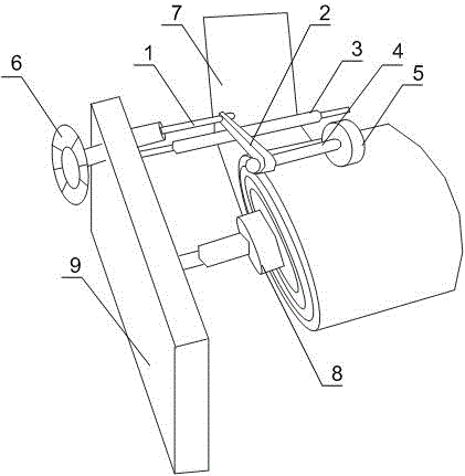
[0016] Such as figure 1 As shown, the present embodiment includes a guide roller 3 and a speed-limiting mechanism, and the guide roller 3 and the speed-limiting mechanism are respectively arranged on an external packaging machine 9, and the speed-limiting mechanism includes a support rod 1, a hand wheel 6, a connecting rod 2 and Press down device, one end of support rod 1 is hinged with the press down device through connecting rod 2, and the other end of support rod 1 is threadedly connected with handwheel 6. The guide roller 3 is spaced from the cylinder 8 of the external packaging machine 9 at a certain distance, so that the packaging material 7 maintains a certain tension. And the speed limiting mechanism can control the rotational speed of the cylinder 8 of the external packaging machine 9, which plays the role of speed limiting; turning the hand wheel 6 drives the support rod 1 to rotate, so that the pressing device moves up and down under the linkage effect of the connec...

Embodiment 2

[0018] Such as figure 1 As shown, this embodiment is based on Embodiment 1, and the pressing device includes a roller 5 and a wheel handle 4 connected to each other, and the wheel handle 4 is connected to the support rod 1 through the connecting rod 2 . The set roller 5 can move together with the roller 8 of the external packaging machine 9, and the interaction force between the roller 5 and the roller 8 can be adjusted by adjusting the handwheel 6. The greater the frictional force between them, the greater the restriction on the speed at which the cylinder 8 rotates, and vice versa.

Embodiment 3

[0020] Such as figure 1 As shown, this embodiment is based on Embodiment 1 and Embodiment 2. As a preference, the roller 5 is a plastic roller. The texture of the plastic roller 5 is relatively soft, and when the relative force between the roller 5 and the roller 8 is relatively large, the roller 5 will not cause damage, imprints and other interference to the packaging material 7 .

[0021] Preferably, the connecting rod 2 is made of aluminum alloy. The connecting rod 2 is arranged between the pressing device and the support rod 1, and is used to connect and support the pressing device. The aluminum alloy material has strong hardness and light weight, which reduces the labor intensity when turning the handwheel 6. It also effectively avoids phenomena such as breakage and fracture of the connecting rod 2 .


PUM


Abstract

The invention discloses a packing material tension keeping structure comprising a guide roller and a speed limit mechanism. The guide roller and the speed limit mechanism are arranged on an external packer which comprises a supporting rod, a hand wheel, a connecting rod and a down-pressing device, one end of the supporting rod is hinged to the down-pressing device through the connecting rod, and the other end of the supporting rod is in threaded connection with the hand wheel. The guide roller and a roller of the external packer are spaced by a certain distance to enable a packing material to keep certain tension. The rotating speed of the roller of the external packer can be controlled through the speed limit mechanism, and speed limit effect is achieved. The hand wheel is rotated to drive the supporting rod to rotate, and the down-pressing device moves up and down under the linkage action of the connecting rod. When the down-pressing device moves downwards, the speed of the roller is limited, and tension reduction of the packing material due to too fast rotation is avoided; when the down-pressing device moves upwards, limit to the speed of the roller is reduced, and feeding requirements of quick packing of the packer can be met.

Description

technical field [0001] The invention relates to the field of packaging, in particular to a tension maintaining structure for packaging materials. Background technique [0002] There are many types of packaging machines, and there are many kinds from different points of view. According to the product state, there are liquid, block, and granular packaging machines; according to the packaging function, there are internal packaging and outsourcing packaging machines; according to the packaging industry, there are packaging machines for food, daily chemicals, and textiles; According to the position, there are single-station and multi-station packaging machines; according to the degree of automation, there are semi-automatic and fully automatic packaging machines. At present, the general packaging machines on the market are composed of packaging equipment, rollers and packaging materials. The packaging materials are wound on the rollers and directly connected to the packaging equ...

Claims


Application Information

Patent Timeline
Patent Type & Authority Applications(China)
IPC IPC(8): B65B41/12B65H23/182
CPCB65B41/12B65H23/1825B65H2515/314
Inventor 熊凌聪
Owner 熊凌聪
Why Eureka
Try Eureka