Elevator door light curtain detection protection device
A detection and protection, elevator door technology, used in elevators, transportation and packaging, elevators and other directions in buildings, can solve the problems of undetectable, cost pressure of elevator enterprises, etc., to improve the detection coverage, various structural forms, The effect of improving safety performance
- Summary
- Abstract
- Description
- Claims
- Application Information
AI Technical Summary
Problems solved by technology
Method used
Image
Examples
no. 1 example
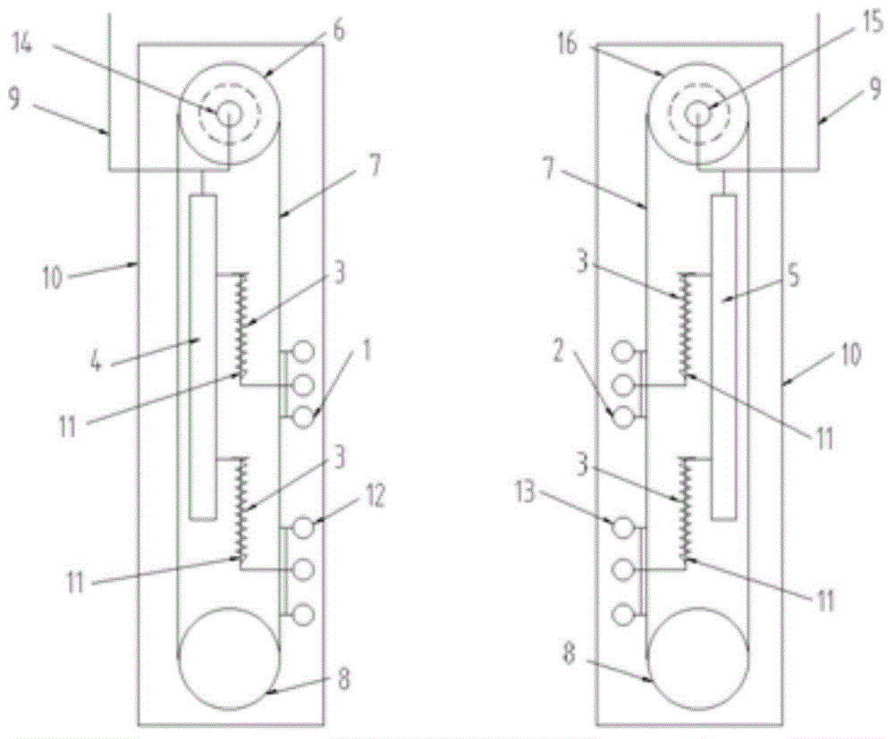
[0046] The first embodiment: the door light curtain detection and protection device of the present invention includes a detection photoeye, a driving mechanism, a transmission mechanism, a control module, and a photoeye position detection unit, such as figure 1 As shown, the detection photocells include a first group of transmitting photocells 1 , a first group of receiving photocells 2 , a second group of transmitting photocells 12 , and a second group of receiving photocells 13 .
[0047] The driving mechanism includes a transmitting end driving motor 6 and a receiving end driving motor 16. Both driving motors contain motor pulleys. Under signal control, the transmitting end driving motor 6 and the receiving end driving motor 16 do periodic reciprocating rotation within a certain angle range.
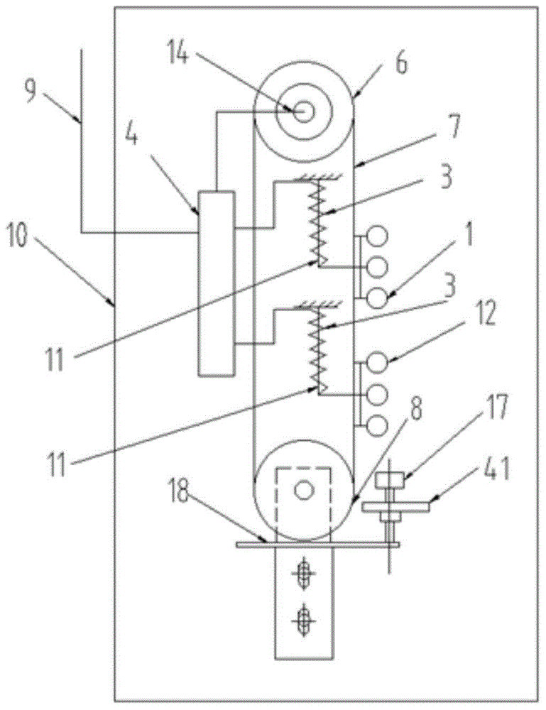
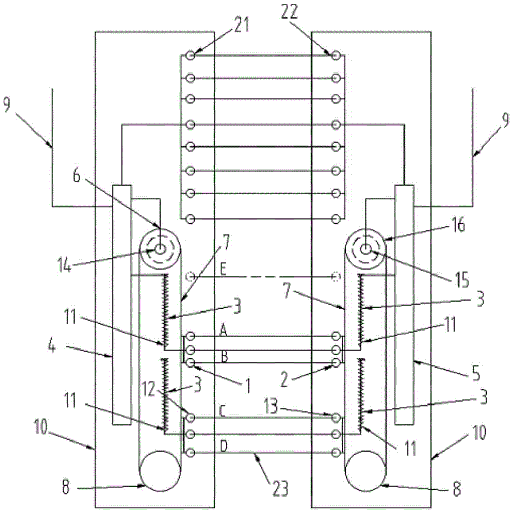
[0048] The transmission mechanism can adopt chain transmission or belt transmission, etc. In this embodiment, the synchronous belt 7 and the pulley are used as the transmission mechani...
no. 2 example
[0059] The second embodiment: adopt the slider crank mechanism instead of the synchronous belt transmission mechanism in the first embodiment, as Figure 4 shown. Runner 28 is installed on the motor shaft of transmitting end motor 27, and motor shaft drives runner 28 to rotate, and a pin shaft is fixedly arranged on runner 28, and one end of connecting rod 24 is installed on the pin shaft of runner 28 by bearing, and another One end is installed on the central axis of the slider 25 through a bearing, and the slider 25 is sleeved on the guide rod 26 through a sliding bearing. A mounting base 42 is fixedly connected to the slider 25, and the detection photoeyes of the transmitting end (the first group of transmitting end optical eyes 1 and the second group of transmitting end optical eyes 12) are installed on the mounting base 42, and the detection optical eyes can be adjusted according to actual needs Multiple groups can be set, and the number of each group can also be set as ...
no. 3 example
[0063] The third embodiment: the one-way rotation of the motor makes the detection light eye move back and forth in a straight line through the cam mechanism, such as Figure 5 Shown, a cam 33 is installed on the motor shaft of the transmitting end motor 27, and the follower that cooperates with the cam 33 is a push rod 34, and a push rod roller 35 is installed at the bottom of the push rod 34, and the push rod 34 is fixed on the fixed side by a sliding bearing. Linear sliding is done in the sliding sleeve 29. The push rod roller 35 presses the edge of the cam 33 under the action of gravity, and rolls along the cam 33 outer edge. The push rod 34 is fixedly connected with the installation seat 42, and the detection photoeyes of the transmitting end (the first group of emission end photoelectric eyes 1 and the second group of emission end photoelectric eyes 12) are installed on the installation seat 42, and the detection photoelectric eyes can be adjusted according to actual nee...
PUM
 Abstract
Description
Claims
Application Information
 - R&D
- Intellectual Property
- Life Sciences
- Materials
- Tech Scout
- Unparalleled Data Quality
- Higher Quality Content
- 60% Fewer Hallucinations
Browse by: Latest US Patents, China's latest patents, Technical Efficacy Thesaurus, Application Domain, Technology Topic, Popular Technical Reports.
© 2025 PatSnap. All rights reserved.Legal|Privacy policy|Modern Slavery Act Transparency Statement|Sitemap|About US| Contact US: help@patsnap.com


