Steam generator and steam cooking utensil with steam generator

A technology for steam generators and cooking utensils, applied in the directions of steam generation, steam generation methods, steam cooking utensils, etc., can solve problems such as low efficiency, low thermal efficiency, heat waste, etc., and achieve increased energy efficiency utilization and uniform steam temperature. , the effect of reducing heat loss

Active Publication Date: 2015-03-18
MIDEA GRP CO LTD +1
View PDF7 Cites 9 Cited by
  • Summary
  • Abstract
  • Description
  • Claims
  • Application Information

AI Technical Summary

Problems solved by technology

[0003] Place the heat pipe on one side or the bottom of the steam generator, since only one side of the heat pipe faces the main load (water), and the other is often directly exposed to the air, its energy utilization is quite poor
[0004] The steam generator that directly soaks the heating pipe into the water can make good use of the heating surface of the heating pipe, but because the heating pipe is basically separated from the generated steam, the steam will condense back quickly after leaving the water surface. It leads to waste of heat, so the thermal efficiency is not high
At the same time, since the heating pipe is in direct contact with water, good anti-rust metal must be used, which will increase the cost relatively.
[0005] As for the combination of the above two methods, it is basically to isolate the heating pipe (or part) of heating steam and heating water, which will be quite difficult to stably control the process of boiling water and the secondary heating of steam
At the same time, these generators themselves lack a good solution for steam heat exchange and heat preservation, so their efficiency is not high

Method used


Image

  • Steam generator and steam cooking utensil with steam generator
  • Steam generator and steam cooking utensil with steam generator
  • Steam generator and steam cooking utensil with steam generator

Examples


Embodiment Construction

[0036] Embodiments of the present invention are described in detail below, examples of which are shown in the drawings, wherein the same or similar reference numerals designate the same or similar elements or elements having the same or similar functions throughout. The embodiments described below by referring to the figures are exemplary and are intended to explain the present invention and should not be construed as limiting the present invention.

[0037] In describing the present invention, it should be understood that the terms "center", "longitudinal", "transverse", "length", "width", "thickness", "upper", "lower", "front", " Orientation or position indicated by "back", "left", "right", "vertical", "horizontal", "top", "bottom", "inner", "outer", "clockwise", "counterclockwise", etc. The relationship is based on the orientation or positional relationship shown in the drawings, and is only for the convenience of describing the present invention and simplifying the descrip...


PUM


Abstract

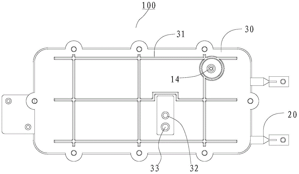
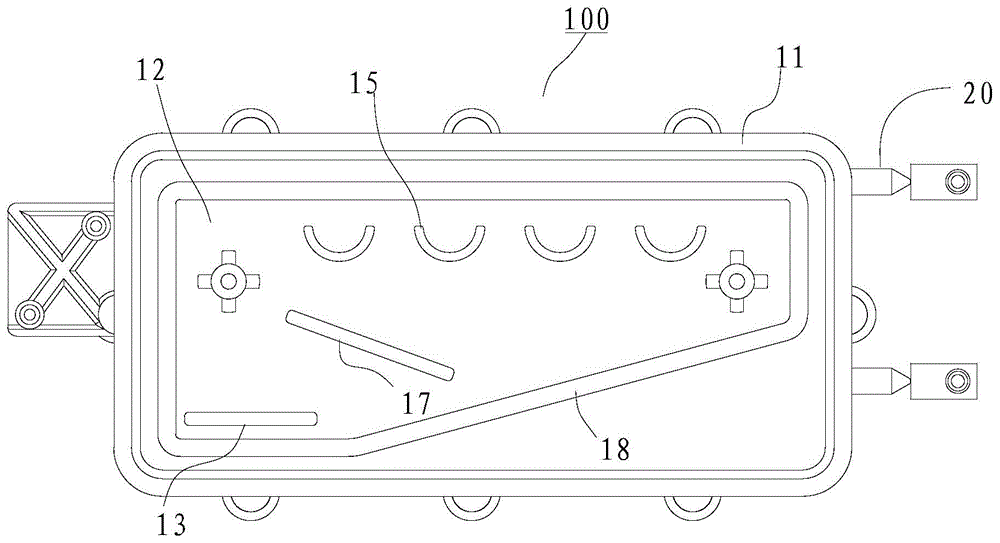
The invention discloses a steam generator and a steam cooking utensil with the steam generator. The steam generator comprises a main body portion, a dummy plate, a heating pipe and a cover plate, wherein the main body portion comprises a frame body, the front end and the rear end of the frame are communicated, the dummy plate divides the frame body into a heating cavity located in front of the dummy plate and a steam cavity located behind the dummy plate, an air inlet communicated with the heating cavity and the steam cavity is formed in the dummy plate, the heating pipe is connected with the dummy plate so as to heat the heating cavity and the steam cavity, the cover plate is arranged at the front end of the frame body so as to seal the heating cavity, a water inlet communicated with the heating cavity is formed in the cover plate, the rear end of the frame body is connected with the steam cooking utensil, and a plurality of steam turbulence portions arranged at intervals are arranged on the rear surface of the dummy plate. According to the steam generator used on the steam cooking utensil, the heating pipe arranged on the dummy plate can simultaneously heat the heating cavity and the steam cavity, and therefore heat loss can be reduced, and energy efficiency utilization rate is improved.

Description

technical field [0001] The invention relates to the technical field of household appliances, in particular to a steam generator used for a steam cooking appliance and the steam cooking appliance. Background technique [0002] The core component of a cooking appliance with steaming function is a steam generator. The steam generator generally includes a boiling water cavity specially used for heating water, some through holes (or nozzles) for spraying steam into the cooking cavity, and the water in the water tank The water is sent to the boiling water cavity of the steam generator through the water delivery device (water pump or electromagnetic valve) for heating, and the steam generated by the boiling water cavity is sprayed out from the through hole. Most steam generators only pay attention to how to prevent boiling water from being sprayed into the cooking cavity and affect the cooking effect, but pay little attention to the energy utilization efficiency of steam generation...

Claims


Application Information

Patent Timeline
Patent Type & Authority Applications(China)
IPC IPC(8): F22B1/28A47J27/04
Inventor 区毅成栾春张国君唐春玉
Owner MIDEA GRP CO LTD
Why Eureka
Try Eureka