Gas appliance and pulse ignition device used for same and pulse ignition control method

A technology of pulse ignition and control method, applied in the field of kitchen appliances, can solve the problems of increased loop resistance, easy self-closing of gas stoves, failure to achieve, etc., to achieve the effect of ensuring reliability

Active Publication Date: 2015-03-18
GUANGDONG MIDEA KITCHEN APPLIANCES MFG CO LTD +1
View PDF3 Cites 4 Cited by
  • Summary
  • Abstract
  • Description
  • Claims
  • Application Information

AI Technical Summary

Problems solved by technology

The existing technical solutions are caused by the production process of the timer, and the general contact resistance is tens of ohms. Since the thermocouple solenoid valve circuit is controlled by the weak current generated by the thermocouple to control the conduction of the solenoid valve, the resistance of the circuit itself is low. If it is relatively large, if you increase the resistance of the timer, the resistance of the entire circuit will increase. During the timing process, especially in the state of low fire, the gas stove is easy to shut down by itself, and the intended purpose cannot be achieved.

Method used


Image

  • Gas appliance and pulse ignition device used for same and pulse ignition control method
  • Gas appliance and pulse ignition device used for same and pulse ignition control method
  • Gas appliance and pulse ignition device used for same and pulse ignition control method

Examples


Embodiment Construction

[0028] Embodiments of the present invention are described in detail below, examples of which are shown in the drawings, wherein the same or similar reference numerals designate the same or similar elements or elements having the same or similar functions throughout. The embodiments described below by referring to the figures are exemplary only for explaining the present invention and should not be construed as limiting the present invention.

[0029] In addition, the terms "first" and "second" are used for descriptive purposes only, and cannot be interpreted as indicating or implying relative importance or implicitly specifying the quantity of indicated technical features. Thus, a feature defined as "first" and "second" may explicitly or implicitly include one or more of these features. In the description of the present invention, "plurality" means two or more, unless otherwise specifically defined.

[0030] In the description of the present invention, it should be noted that...


PUM


Abstract

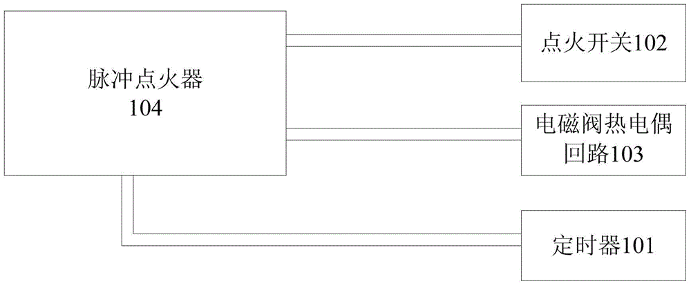
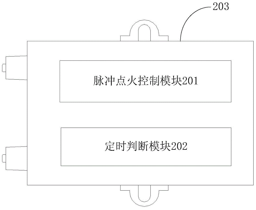
The invention discloses a gas appliance, a pulse ignition device used for the same, and a pulse ignition control method, wherein the pulse ignition device used for the gas appliance comprises: a timer; an ignition switch; a solenoid valve thermocouple loop in parallel connection with the timer; and a pulse igniter respectively connected with the timer, the ignition switch, and the solenoid valve thermocouple loop. When the ignition switch is triggered, the pulse igniter controls a solenoid valve in the solenoid valve thermocouple loop to open; the timer is determined to start timing while the timing signal of the timer is detected; and the solenoid valve is controlled to close when timing ending of the timer is detected. According to the invention, through the parallel connection of the timer with the solenoid valve thermocouple loop, no automatic flame-out phenomenon occurs in the timing period when the solenoid valve thermocouple loop is normal, and thus the reliability of the timing function of the gas appliance is guaranteed.

Description

technical field [0001] The invention relates to the technical field of kitchen appliances, in particular to a gas appliance, a pulse ignition device and a pulse ignition control method for the gas appliance. Background technique [0002] At present, the timing function of the existing cooker is to connect the timer in series with the thermocouple electromagnetic valve circuit. When the timer is disconnected, the gas appliance is turned off. The existing technical solutions are caused by the production process of the timer, and the general contact resistance is tens of ohms. Since the thermocouple solenoid valve circuit is controlled by the weak current generated by the thermocouple to control the conduction of the solenoid valve, the resistance of the circuit itself is low. If it is relatively large, if you increase the resistance of the timer, the resistance of the entire circuit will increase. During the timing process, especially in the state of low fire, the gas stove wi...

Claims


Application Information

Patent Timeline
Patent Type & Authority Applications(China)
IPC IPC(8): F24C3/10F24C3/12
CPCF24C3/103F24C3/126
Inventor 肖斌朱世平李志伟
Owner GUANGDONG MIDEA KITCHEN APPLIANCES MFG CO LTD
Why Eureka
Try Eureka