
Sampling circuit, switching power supply control circuit, switching power supply and sampling method

A technology of switching power supply and sampling circuit, which is applied in the direction of control/regulation system, measuring current/voltage, electrical components, etc. It can solve the problems of inaccurate feedback voltage and low precision of constant voltage control of switching power supply, so as to improve the precision of constant voltage control , high voltage stability, and the effect of reducing sampling errors

Active Publication Date: 2015-03-18
BYD SEMICON CO LTD
View PDF5 Cites 13 Cited by
  • Summary
  • Abstract
  • Description
  • Claims
  • Application Information

AI Technical Summary

Problems solved by technology

[0005] The technical problem to be solved by the present invention is to provide a sampling circuit, a switching power supply control circuit, a switching power supply and a sampling method for the defects that the feedback voltage collected by the switching power supply is not accurate enough in the prior art and the constant voltage control accuracy of the switching power supply is low , so that the feedback voltage in the switching power supply can be accurately collected and the constant voltage control accuracy of the switching power supply can be improved

Method used


Image

  • Sampling circuit, switching power supply control circuit, switching power supply and sampling method
  • Sampling circuit, switching power supply control circuit, switching power supply and sampling method
  • Sampling circuit, switching power supply control circuit, switching power supply and sampling method

Examples


Embodiment Construction

[0033] In order to make the technical problems, technical solutions and beneficial effects solved by the present invention clearer, the present invention will be further described in detail below in conjunction with the accompanying drawings and embodiments. It should be understood that the specific embodiments described here are only used to explain the present invention, not to limit the present invention.

[0034] In describing the present invention, it should be understood that the terms "longitudinal", "transverse", "upper", "lower", "front", "rear", "left", "right", "vertical", The orientation or positional relationship indicated by "horizontal", "top", "bottom", "inner", "outer", etc. are based on the orientation or positional relationship shown in the drawings, and are only for the convenience of describing the present invention and simplifying the description, rather than Nothing indicating or implying that a referenced device or element must have a particular orienta...


PUM


Abstract

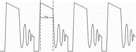
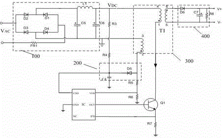
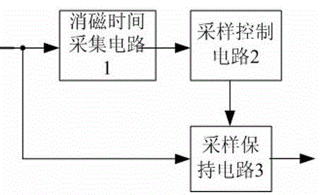
The invention provides a sampling circuit, a switching power supply control circuit, a switching power supply and a sampling method. The sampling circuit comprises a demagnetization time acquisition circuit which is used for acquiring transformer demagnetization time TDS of the switching power supply in one switching period and transmitting the demagnetization time to a sampling control circuit; the sampling control circuit which is used for outputting predetermined clock pulse CLK according to the demagnetization time TDS so as to control sampling time of a sampling holding circuit, wherein pulse width W1 of the predetermined clock pulse CLK is less than the demagnetization time TDS; and the sampling holding circuit which is used for acquiring instant feedback voltage VF of the switching power supply at a predetermined time point under the control of the clock pulse CLK and holding feedback voltage VF so as to output an analog single with amplitude of VF, wherein the predetermined time point is the instant at which the switching power supply starts to work continuously for a time period of W1 in a switching period after one switching period. Feedback voltage in the switching power supply can be accurately acquired and constant voltage control precision of the switching power supply can be enhanced.

Description

technical field [0001] The invention relates to the field of power supplies, in particular to a sampling circuit, a switching power supply control circuit, a switching power supply and a sampling method. Background technique [0002] At present, a large number of electrical appliances need to use low-voltage DC power supply. For example, almost all household appliances need to use low-voltage DC power supply for main power supply or control part power supply. However, due to the consideration of the loss of voltage transmission in the power grid, the grid can only provide 220V ( Some countries are 110V) AC power supply. Therefore, a high-efficiency, cost-effective AC-DC (AC-DC) converter becomes an indispensable part. Traditional AC-DC production is usually implemented with linear converters, but linear converters are being phased out due to their huge size, heavy weight, low-voltage conversion efficiency, and no longer obvious cost advantages. Among the current AC-DC conv...

Claims


Application Information

Patent Timeline
IPC IPC(8): G01R19/00H02M1/08H02M3/335
Inventor 叶文辉侯永军张海泉
Owner BYD SEMICON CO LTD
Learn More