Position indicator and position indicating method for marine equipment

A technology of marine equipment and position indicator, which is applied to instruments, measuring devices, satellite radio beacon positioning systems, etc., can solve the problems of loss of marine equipment, high price, complex structure, etc., and achieves a large depth range, reduces power consumption, Stable performance

Inactive Publication Date: 2015-03-18
SHENYANG INST OF AUTOMATION - CHINESE ACAD OF SCI
View PDF9 Cites 9 Cited by
  • Summary
  • Abstract
  • Description
  • Claims
  • Application Information

AI Technical Summary

Problems solved by technology

[0002] At present, the common marine equipment that needs to be positioned usually comes with GPS and Iridium equipment to send the location information to the mother ship or the control center. However, when the marine equipment fails to surface or the GPS and Iridium equipment fails When the location information cannot be sent out, the marine equipment will often be lost, such as underwater submersible buoys and AUV equipment for long-term monitoring of marine information.
[0003] However, most depth sensors are in the form of pressure-sensitive elements (stainless steel, ceramics, etc.) to continuously monitor depth information in real time, with complex structures, high energy consumption, and high prices.

Method used


Image

  • Position indicator and position indicating method for marine equipment
  • Position indicator and position indicating method for marine equipment
  • Position indicator and position indicating method for marine equipment

Examples


Embodiment Construction

[0033] The present invention will be described in further detail below in conjunction with the accompanying drawings.

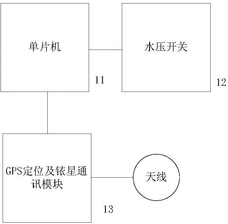
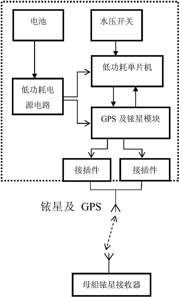
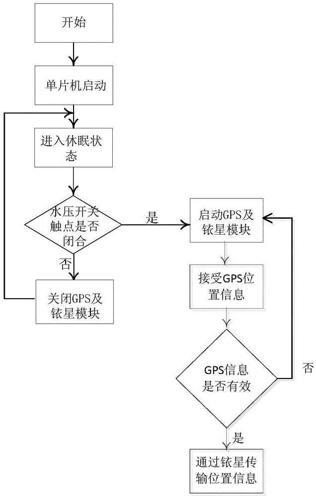
[0034] The method of the present invention for providing the position indication function for marine equipment: based on the single-chip microcomputer to collect the water pressure switch signal, then judge whether the carrier is floating on the water surface according to the water pressure switch signal, and if it floats on the water surface, start the GPS positioning and Iridium communication module, and the carrier coordinates Information is sent via Iridium to the mother ship or control center.

[0035] In this embodiment, the single-chip microcomputer detects the signal of the water pressure switch to judge whether the carrier is about to emerge from the water, and to start or close the GPS positioning and the work of the Iridium communication module. Use the water pressure switch to judge whether the carrier has surfaced. The water pressure switch is a ...


PUM


Abstract

The invention belongs to the technical field of electromechanical control in a high-pressure marine environment, and particularly relates to a position indicator for marine equipment. The position indicator comprises a power supply circuit, a water pressure switch, a single chip microcomputer, a GPS and iridium satellite positioning communication module, and an antenna, wherein the power supply circuit is connected with a battery, the water pressure switch, the single chip microcomputer, the GPS and iridium satellite positioning communication module and the antenna are connected in sequence, and the power supply circuit is connected with the single chip microcomputer and the GPS and iridium satellite positioning communication module. The position indicating method comprises the following steps: when a contact in a switching assembly of the water pressure switch is closed, the single chip microcomputer is brought into a working state, and the GPS and iridium satellite positioning communication module is started to work, and whether GPS information is effective or not is judged; if GPS position information deviates from the last position information by more than 10 meters, the GPS information is judged as effective, and the GPS position information is sent; and if the GPS position information does not deviate from the last position information by more than 10 meters, the GPS information is judged as ineffective, and the last detected position information is used as effective information of positioning and does not need to be resent. The position indicator is not in electrical connection with marine environment to which the position indicator is attached, so that interference to the marine equipment is avoided, and the influence of power failure of the main system of the marine equipment to the work of the position indicator system is avoided.

Description

technical field [0001] The invention relates to a technology for providing a position display function for marine equipment, in particular to a method and a control device for providing the geographic location of marine equipment to a mother ship or a control center. Background technique [0002] At present, the common marine equipment that needs to be positioned usually comes with GPS and Iridium equipment to send the location information to the mother ship or the control center. However, when the marine equipment fails to surface or the GPS and Iridium equipment fails When the location information cannot be sent out, the marine equipment will often be lost, such as underwater submersibles and AUV equipment for long-term monitoring of marine information. [0003] However, most depth sensors are in the form of pressure-sensitive elements (stainless steel, ceramics, etc.) to continuously monitor depth information in real time, with complex structures, high energy consumption,...

Claims


Application Information

Patent Timeline
Patent Type & Authority Applications(China)
IPC IPC(8): G01S19/01G01S19/02
CPCG01S19/01
Inventor 陈琦郭威
Owner SHENYANG INST OF AUTOMATION - CHINESE ACAD OF SCI
Why Eureka
Try Eureka