
Wireless power supply method, power supply device and power supply system

A wireless power supply and control device technology, applied in circuit devices, electromagnetic wave systems, circuits, etc., can solve problems such as poor coupling between transmitting coils and receiving coils, electromagnetic leakage, and incomplete coverage of receiving coils, so as to improve power supply efficiency and coupling sexual effect

Active Publication Date: 2015-03-18
HAIER GROUP TECHN R&D CENT +1
View PDF4 Cites 3 Cited by
  • Summary
  • Abstract
  • Description
  • Claims
  • Application Information

AI Technical Summary

Problems solved by technology

[0002] Wireless power supply technology achieves wireless energy transmission by setting corresponding electromagnetic transmitting coils and electromagnetic receiving coils in the wireless power supply device and electrical equipment respectively, but different electrical equipment has different power and size, so the size of the receiving coil is also different. Different, the transmitting coil of the current wireless power supply device is a fixed single-coil structure. When the receiving coil in the electrical equipment is smaller than the transmitting coil, the receiving coil cannot be completely covered due to the large effective working area of ​​the transmitting coil, resulting in electromagnetic leakage. , if a metal foreign object is placed in the uncovered area, it will become hot due to the eddy current loss caused by electromagnetic leakage, and there is a certain safety hazard; in addition, the coupling between the transmitting coil and the receiving coil is poor, and the energy transmission efficiency is low

Method used


Image

  • Wireless power supply method, power supply device and power supply system
  • Wireless power supply method, power supply device and power supply system
  • Wireless power supply method, power supply device and power supply system

Examples


Embodiment 1

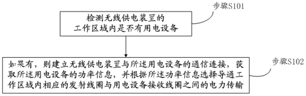
[0021] refer to figure 1 , this embodiment provides a wireless power supply method, including:

[0022] Step S101, detecting whether there is any electrical equipment in the working area of ​​the wireless power supply device;

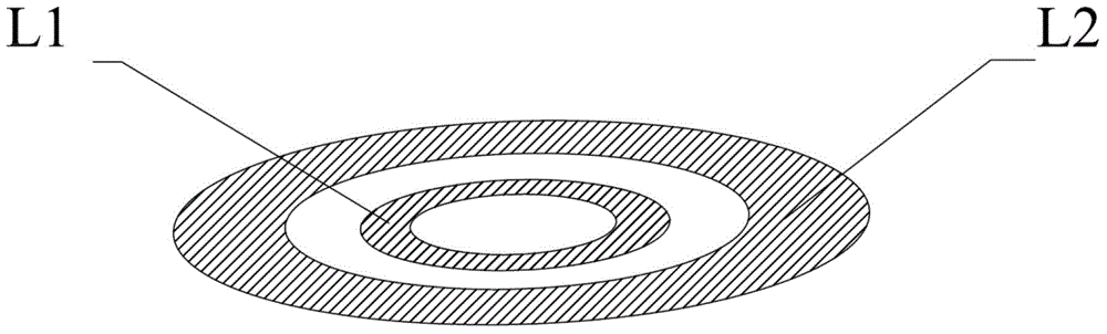
[0023] The working area includes a plurality of transmitting coils of different sizes arranged concentrically;

[0024] Step S102, if yes, establish a communication connection between the wireless power supply device and the power-consuming device, acquire power information of the power-consuming device, and select and turn on the corresponding transmission in the working area according to the power information Power transmission between the coil and the receiving coil of the powered device.

[0025] This embodiment does not limit the control processing method for detecting that there is no electrical equipment in the working area, for example, an optional implementation manner: continue to detect whether there is electrical equipment in the working a...

Embodiment 2

[0054] refer to Figure 4 , this embodiment provides a wireless power supply device, including:

[0055] A working area 201 formed by a plurality of concentrically arranged transmitting coils of different sizes;

[0056] The control device 202 is configured to control and detect whether there is an electrical device in the working area, control to establish a communication connection with the electrical device when there is an electrical device in the working area, and control to obtain the information of the electrical device power information, and select to turn on the power transmission between the corresponding transmitting coil in the working area and the receiving coil of the electric device according to the power information.

[0057] As an optional implementation, the wireless power supply device provided in this embodiment also includes a giant magnetoresistance sensor 203, which is used to detect whether there is an electric device in the working area; a receiving c...

Embodiment 3

[0074] refer to Figure 5 , this embodiment provides a wireless power supply system, including:

[0075] The wireless power supply device 301 and the electric device 302, the electric device 302 is provided with a receiving coil for coupling with the transmitting coil in the wireless power supply device 301 for power transmission.

[0076] For the structure and principle of the wireless power supply device 301 , please refer to Embodiment 2, which will not be repeated here.

[0077] The electrical equipment 301 is also provided with a signal transmitting end 303 for communicating with the signal receiving end in the wireless power supply device 301 and sending information to the signal receiving end, the information including the power information of the electrical equipment itself.

[0078] The wireless power supply system provided in this embodiment can select a suitable transmitting coil for power transmission according to the information of the electrical equipment, is co...


PUM

PropertyMeasurementUnit
Diameteraaaaaaaaaa
Outer diameteraaaaaaaaaa

Abstract

A wireless power supply method, a wireless power supply apparatus and a wireless power supply system. The method comprises: detecting whether there is power consumption equipment in the working area of the wireless power supply apparatus, the working area comprising a plurality of differently-sized and concentrically-arrayed transmitting coils; if there is, establishing a communicative connection between the wireless power supply apparatus and the power consumption equipment, obtaining the power information of the power consumption equipment, and, on the basis of the power information, choosing to enable electric power transmission between the corresponding transmitting coils in the working area and a receiving coil of the power consumption equipment; and improving the coupling of the transmitting coils and the receiving coil so as to improve the efficiency of power supply.

Description

technical field [0001] The present invention relates to the technical field of wireless power supply, in particular to a wireless power supply method, a power supply device and a power supply system. Background technique [0002] Wireless power supply technology achieves wireless energy transmission by setting corresponding electromagnetic transmitting coils and electromagnetic receiving coils in the wireless power supply device and electrical equipment respectively, but different electrical equipment has different power and size, so the size of the receiving coil is also different. Different, the transmitting coil of the current wireless power supply device is a fixed single-coil structure. When the receiving coil in the electrical equipment is smaller than the transmitting coil, the receiving coil cannot be completely covered due to the large effective working area of ​​the transmitting coil, resulting in electromagnetic leakage. , If a metal foreign object is placed in th...

Claims


Application Information

Patent Timeline
IPC IPC(8): H02J17/00
CPCH02J17/00H01F27/2871H01F38/14H02J50/12H02J7/00034H02J50/005H02J50/60H02J50/80H02J50/40H02J50/402
Inventor 李聃龙海岸娄兵兵
Owner HAIER GROUP TECHN R&D CENT
Features
  • Generate Ideas
  • Intellectual Property
  • Life Sciences
  • Materials
  • Tech Scout
  • Unparalleled Data Quality
  • Higher Quality Content
  • 60% Fewer Hallucinations
Learn More