Check patentability & draft patents in minutes with Patsnap Eureka AI!

Rotor position sensor

A technology of rotor position and sensor, applied in the direction of electromechanical devices, electrical components, structural connections, etc., to achieve the effect of saving structural space

Active Publication Date: 2015-03-18
ZF FRIEDRICHSHAFEN AG
View PDF6 Cites 0 Cited by
  • Summary
  • Abstract
  • Description
  • Claims
  • Application Information

AI Technical Summary

Problems solved by technology

[0004] However, it is disadvantageous in the prior art that the rotor carrier must have an additional molded-in ring element, which also extends in the axial direction, so that an axial space requirement for mounting the rotor position sensor is necessary

Method used


Image

  • Rotor position sensor
  • Rotor position sensor
  • Rotor position sensor

Examples


Embodiment Construction

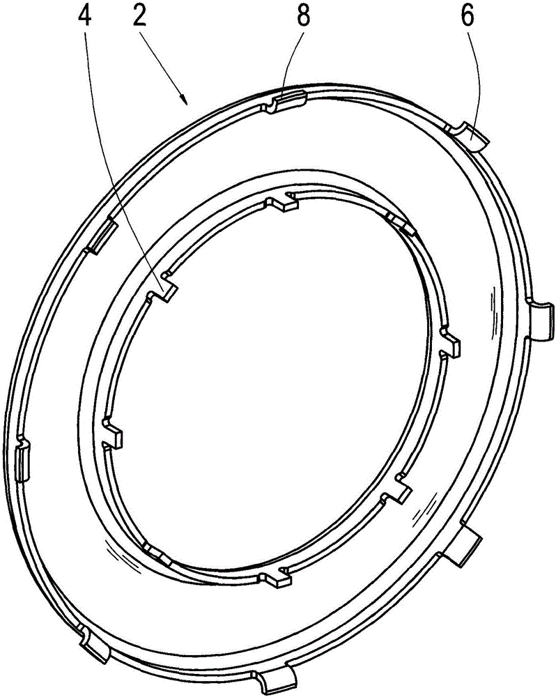
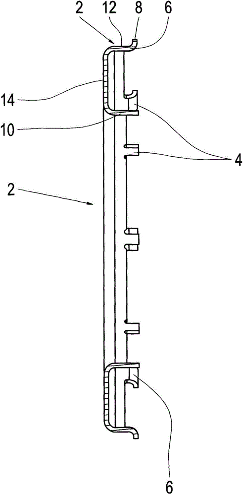
[0024] Figure 1 schematically in perspective view ( Figure 1a ) and in section view ( Figure 1b ) shows the rotor position sensor-rotor frame 2 according to the invention. as especially available from Figure 1a As can be seen in the figure, the rotor position sensor-rotor frame 2 according to the invention has substantially axially extending projections 4, 6, such as Figure 1a Arranged as shown on the inner periphery (projection 4 ) of the rotor position sensor rotor carrier 2 and on its outer periphery (projection 6 ). In this case, the projection 6 also has, at the outer circumference, a projection 8 extending radially outward.

[0025] Furthermore, especially Figure 1b The sectional illustration in FIG. 2 shows that the rotor position sensor rotor frame is C-shaped and has a first side arm 10 and a second side arm 12 , which are connected to each other by radially extending connecting elements 14 . In addition, if available from Figure 1b As can be seen in , the ex...


PUM


Abstract

The invention relates to a motor, particularly a rotor position sensor-rotor support (2) for the electric machines of motor vehicles. On one hand, a rotor support (28) is connected with the rotor position sensor-rotor support (2) in an un-rotatable manner. On the other hand, the rotor support (28) is connected with a rotor position sensor rotor (16) and / or the rotor support (28) in an un-rotatable manner. The rotor position sensor-rotor support (2) is preferably, substantially and axially provided with at least one projection (4; 6). The at least one projection (4; 6) is engaged with the at least one receptacle (20; 32) of the rotor position sensor rotor (16) and / or the rotor support (28). The invention also relates to a rotor position sensor rotor (16) and a rotor support (28) for an electric machine.

Description

technical field [0001] The invention relates to a rotor position sensor and in particular to a rotor position sensor-rotor carrier for an electric machine, which can be connected to the rotor carrier in a non-rotatable manner on the one hand and can be connected to the rotor position on the other hand. The sensor-rotor is connected in a rotationally fixed manner, and the invention also relates to a rotor position sensor-rotor carrier of this type and a rotor carrier with a rotor position sensor-rotor carrier of this type. Background technique [0002] In electrical machines, especially permanent magnet excited synchronous electrical machines, it is necessary to obtain the rotational position of the rotor to drive the electrical machine. This type of position is usually determined by a so-called rotor position sensor, which in turn consists of a rotor position sensor-rotor and a rotor position sensor-stator. In this case, the rotor position sensor rotor can be connected in a...

Claims


Application Information

Patent Timeline
IPC IPC(8): H02K11/00
CPCH02K11/0021H02K11/215
Inventor C·布吕克纳J·布尔黑勒
Owner ZF FRIEDRICHSHAFEN AG
Features
  • R&D
  • Intellectual Property
  • Life Sciences
  • Materials
  • Tech Scout
  • Unparalleled Data Quality
  • Higher Quality Content
  • 60% Fewer Hallucinations
Learn More