Optical line terminal and optical network unit

A technology of optical line terminal and optical network unit, which is applied in the direction of electrical components, multiplexing system selection device, electromagnetic wave transmission system, etc., can solve the problems that cannot meet the requirements of TWDM-PON band, achieve convenient implementation, reduce Cost, effect of improving accuracy

Active Publication Date: 2015-03-18
ALCATEL LUCENT SHANGHAI BELL CO LTD
View PDF8 Cites 7 Cited by
  • Summary
  • Abstract
  • Description
  • Claims
  • Application Information

AI Technical Summary

Problems solved by technology

The current coarse wave demultiplexer cannot meet the band requirements in TWD

Method used


Image

  • Optical line terminal and optical network unit
  • Optical line terminal and optical network unit
  • Optical line terminal and optical network unit

Examples


Embodiment Construction

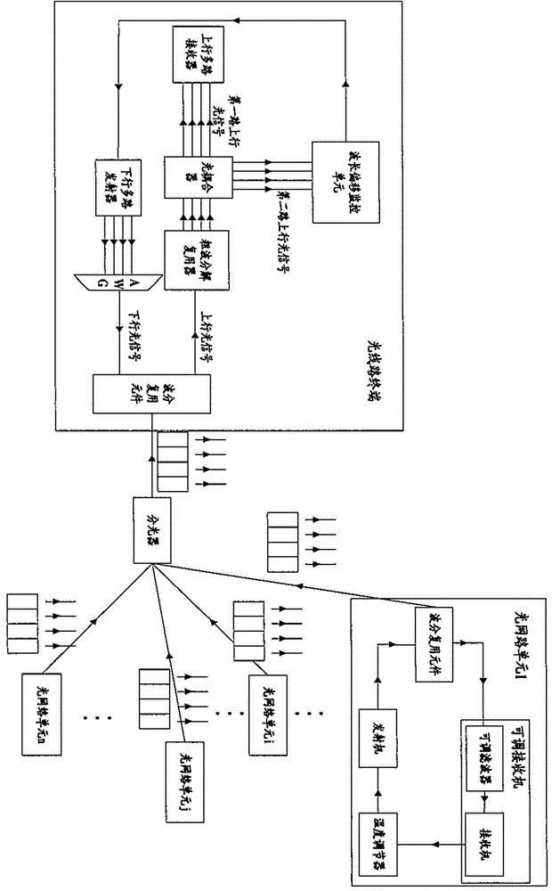
[0019] figure 1 The optical network architecture of TWDM-PON according to an embodiment of the present invention is shown. Such as figure 1 As shown, the optical line terminal is connected to a plurality of optical network units 1...n through an optical splitter, wherein the structure of the optical network unit 1 is shown in detail, and the structures of other optical network units are similar to the structure of the optical network unit 1 .

[0020] In this TWDM-PON, 4 mutually different upstream wavelengths and 4 mutually different downstream wavelengths are used. In other examples, other numbers of upstream and downstream wavelengths may also be applied.

[0021] The OLT according to the present invention includes a wavelength division multiplexing element for multiplexing and demultiplexing uplink optical signals and downlink optical signals. In the optical line terminal, the coarse wavelength division multiplexer is coupled with the wavelength division multiplexing el...


PUM


Abstract

The invention provides an optical line terminal and an optical network unit. The optical line terminal comprises a wavelength division multiplexing element, a coarse wavelength division multiplexer, an optical coupler, an uplink multi-channel receiver, a downlink multi-channel transmitter and a wavelength shift monitoring unit; the wavelength division multiplexing element is used for multiplexing and demultiplexing uplink optical signals and downlink optical signals; the coarse wavelength division multiplexer is used for filtering and demultiplexing the uplink optical signals; the optical coupler is used for dividing the filtered and demultiplexed uplink optical signals into a first channel of uplink optical signals and a second channel of uplink optical signals; the uplink multi-channel receiver is used for receiving the first channel of uplink optical signals; the downlink multi-channel transmitter transmits the downlink optical signals via an arrayed waveguide grating and the wavelength division multiplexing element; the wavelength shift monitoring unit is used for detecting whether the wavelength of the second channel of uplink optical signals exceeds a boundary threshold, and when the wavelength of the second channel of uplink optical signals exceeds the boundary threshold, optical network units which need to adjust uplink wavelength are determined and indication information is included into the downlink optical signals of the downlink multi-channel transmitter.

Description

technical field [0001] The present invention relates to a time division wavelength division multiplexing passive optical network, in particular to an optical line terminal and an optical network unit for a time division wavelength division multiplexing passive optical network, and further relates to a method for detecting wavelength crossing, and a rough A method for adjusting the wavelength of an uplink optical signal. Background technique [0002] Time and Wavelength Division Multiplexed-Passive Optical Network (TWDM-PON) is considered by the industry as the main solution for NG-PON2. It is not only applicable to the capacity of 40GbMs, but also considered to be suitable for the development requirements of future optical networks, for example, applicable to optical networks with a capacity above 100Gbit / s. [0003] Recently, wavelength planning and wavelength spacing are two hot topics in FSAN (Full Service Access Network, full service access network). Tunable lasers and...

Claims


Application Information

Patent Timeline
IPC IPC(8): H04B10/40H04B10/075H04Q11/00
Inventor 桂林
Owner ALCATEL LUCENT SHANGHAI BELL CO LTD
Why Eureka
Try Eureka