High efficiency reaction tank

A reaction tank, high-efficiency technology, applied in the field of mechanical equipment, can solve the problems of unfavorable reaction, low stirring efficiency, insufficient stirring, etc., and achieve the effect of being suitable for popularization and use, increasing the weight of the tank body, and high stirring efficiency

Inactive Publication Date: 2015-03-25
上海伟阳纸业有限公司
View PDF1 Cites 1 Cited by
  • Summary
  • Abstract
  • Description
  • Claims
  • Application Information

AI Technical Summary

Problems solved by technology

[0002] With the development of social production and the rapid development of the machinery industry, a large number of industrial tools are produced and used. With the extensive development of the reaction industry, the role of the reaction tank in the operation cannot be ignored. The application number is CN 201310160570.2, which discloses a The novel reaction tank includes a tank body, a hollow tube is vertically arranged in the tank body, a screw conveyor is arranged in the hollow tube, the screw conveyor is driven by a motor, and the bottom of the hollow tube is a certain distance away from the bottom of the tank body. When the present invention is in use, The material near the hollow tube on the upper part of the tank can be sucked into the hollow tube through the motor-driven screw conveyor, and the material can be discharged from the lower end of the hollow tube through screw conveying, and mixed with the material at the bottom of the tank, so that the upper and lower layers of the reaction tank The materials can be fully mixed, which improves the efficiency of the reaction tank and effectively prevents the waste of raw materials and the occurrence of potential safety hazards. However, when the reaction tank is used for reaction operations, there are no at least two motors to drive it, so the stirring efficiency is not high, and the reaction liquid cannot flow between the impellers. If the mixing is not enough, the reaction is not complete, and there is no distributing device, which is not conducive to the reaction and the efficiency is low

Method used


Image

  • High efficiency reaction tank
  • High efficiency reaction tank

Examples


Embodiment Construction

[0014] In order to make the technical means, creative features, goals and effects achieved by the present invention easy to understand, the present invention will be further described below in conjunction with specific illustrations.

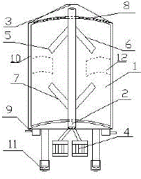
[0015] Such as figure 1 and figure 2 As shown, a high-efficiency reaction tank according to the present invention includes a tank body 1 and a rotating shaft 2. The side of the tank body 1 is provided with a feed port 3, and the rotating shaft 2 is arranged inside the tank body. The shaft 2 is connected with at least two motors 4, the rotating shaft 2 is provided with an impeller 5, the impeller 5 includes an upper impeller 6 and a lower impeller 7, and the upper impeller 6 and the lower impeller 7 are 15 to 20 cm away from the tank body, The feeding port 3 is provided with a distributing pipe 8, and the bottom of the tank body 1 is provided with at least 2 discharge ports 9. During the reaction operation, the rotating shaft is driven by at le...


PUM


Abstract

The invention discloses a high efficiency reaction tank, which comprises a tank body and a rotating shaft. The side of the tank body is provided with a feed inlet, the rotating shaft is arranged at inside the tank body, the rotating shaft is connected to at least 2 motors, the rotating shaft is provided with an impeller, the impeller consists of an upper impeller and a lower impeller, and the upper impeller and the lower impeller are 15-20cm away from the tank body. The feed inlet is provided with a distributing pipe, and the tank bottom is equipped with at least two discharge ports. During reaction operation, the rotating shaft rotates driven by the at least 2 motors simultaneously, the stirring efficiency is high, the upper impeller and the lower impeller work at the same time, so that the reaction liquid is fully stirred and mixed between the two impellers, the reaction is complete, the distributing pipe enables even and smooth feeding, thus being conducive to proceeding of reaction. With the advantages of reasonable structure, convenience and simplicity, the high efficiency reaction tank is suitable for popularization and use.

Description

technical field [0001] The invention relates to the field of mechanical equipment, in particular to a high-efficiency reaction tank. Background technique [0002] With the development of social production and the rapid development of the machinery industry, a large number of industrial tools are produced and used. With the extensive development of the reaction industry, the role of the reaction tank in the operation cannot be ignored. The application number is CN 201310160570.2, which discloses a The new reaction tank includes a tank body, a hollow tube is vertically arranged in the tank body, a screw conveyor is arranged in the hollow tube, the screw conveyor is driven by a motor, and the bottom of the hollow tube is a certain distance away from the bottom of the tank body. When the present invention is in use, The material near the hollow tube on the upper part of the tank can be sucked into the hollow tube through the motor-driven screw conveyor, and the material is disch...

Claims


Application Information

Patent Timeline
Patent Type & Authority Applications(China)
IPC IPC(8): B01J19/18
CPCB01J19/18B01J19/0066B01J2219/00022B01J2219/185
Inventor 简文秀
Owner 上海伟阳纸业有限公司
Why Eureka
Try Eureka