Hydraulic tensioner

A tensioner, hydraulic technology, applied to belts/chains/gears, mechanical equipment, transmissions, etc., to achieve high hardness, restrain elastic deformation, and low linear expansion coefficient

Inactive Publication Date: 2008-08-06
TSUBAKIMOTO CHAIN CO
View PDF0 Cites 3 Cited by
  • Summary
  • Abstract
  • Description
  • Claims
  • Application Information

AI Technical Summary

Problems solved by technology

[0006] However, in the above-mentioned conventional hydraulic tensioner 500, since the ball guide 542 is made of synthetic resin, the ball guide 542 may be elastically deformed by the high pressure in the high-pressure oil chamber R, Or expansion and contraction accompanying the temperature change of the oil in the engine room

Method used


Image

  • Hydraulic tensioner
  • Hydraulic tensioner
  • Hydraulic tensioner

Examples


Embodiment Construction

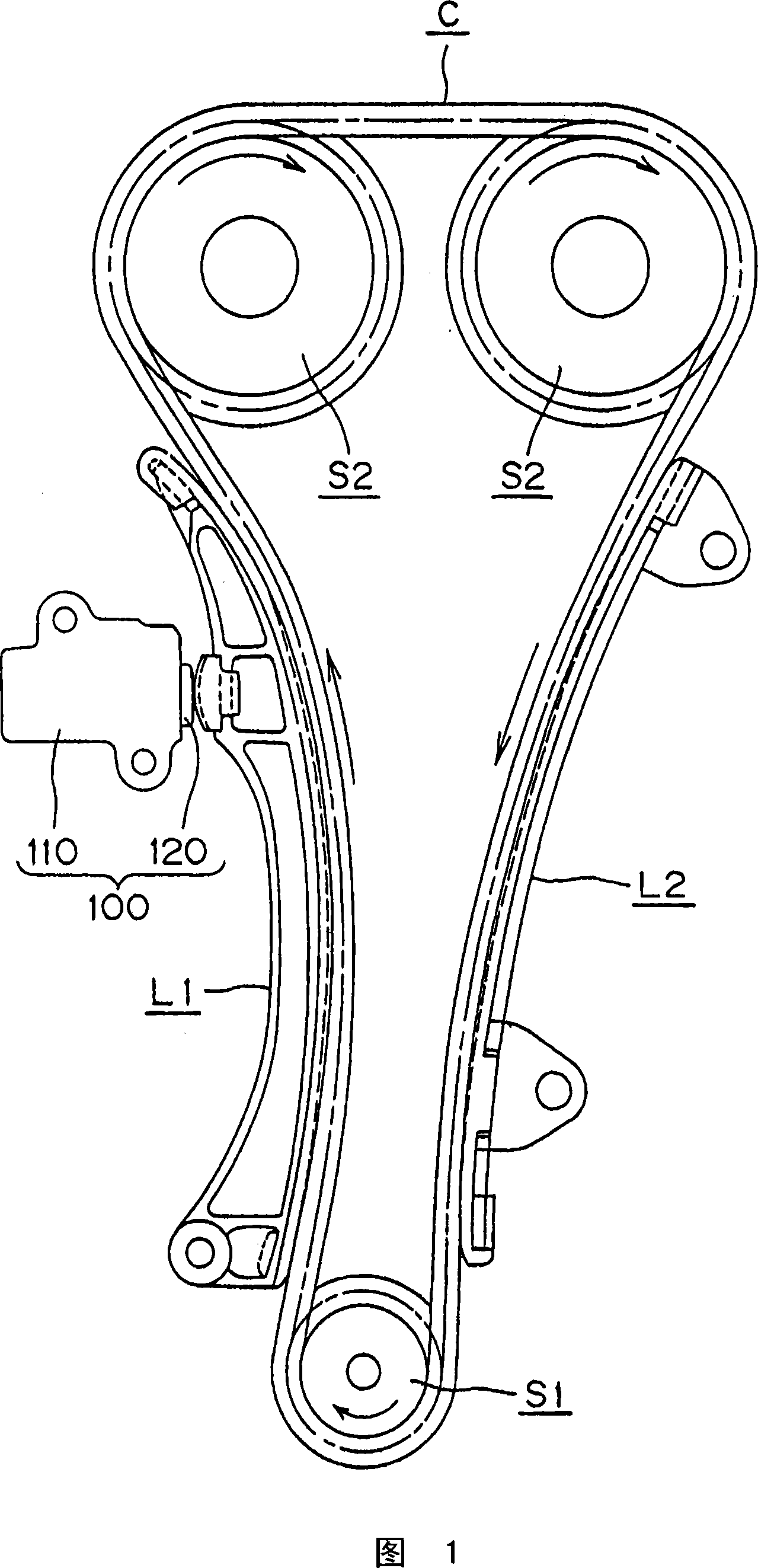
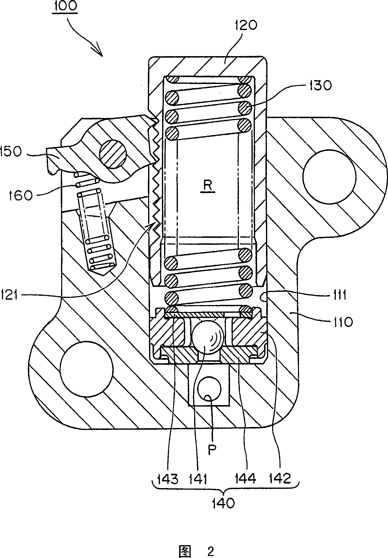
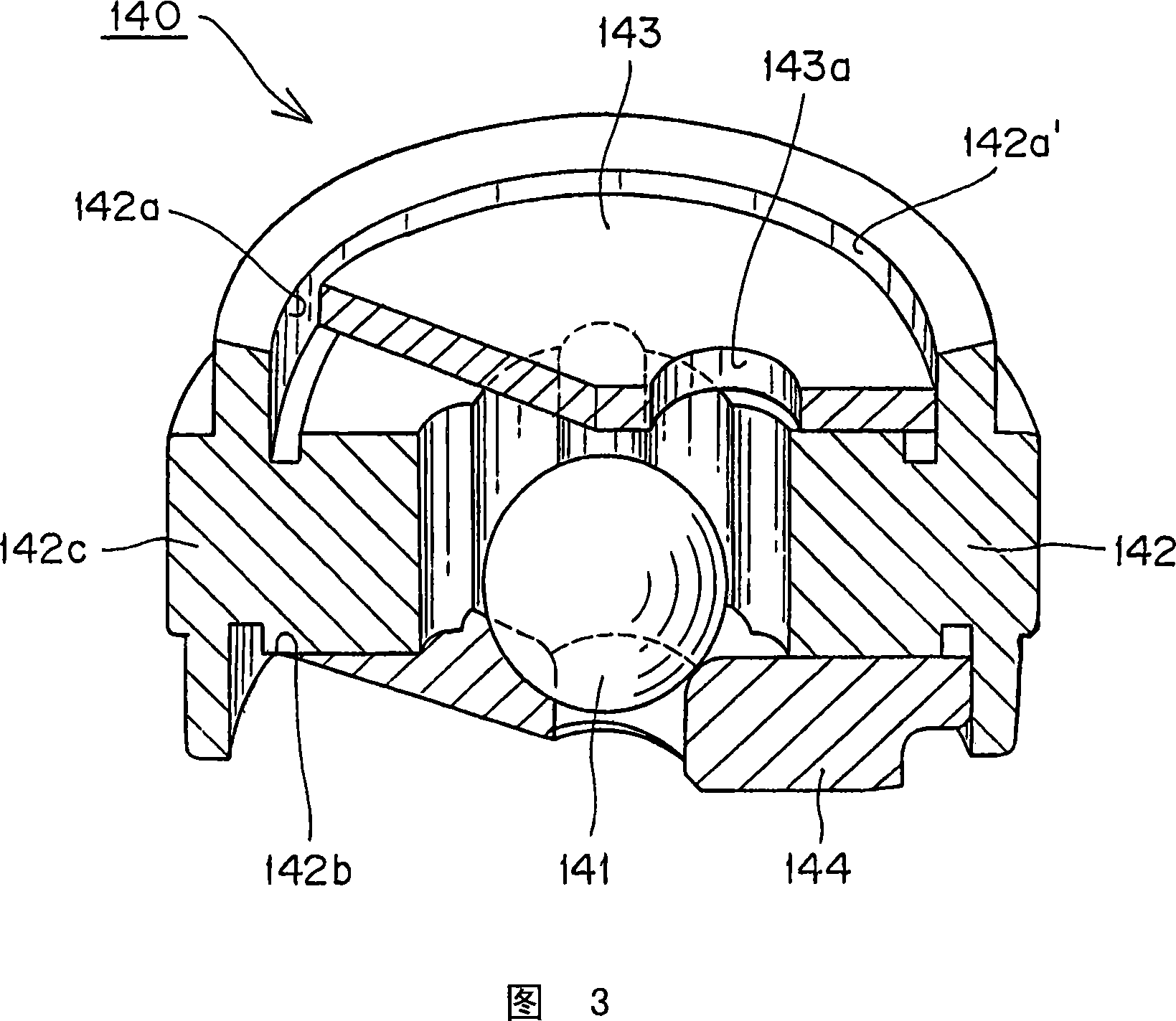
[0057] The hydraulic tensioner of the present invention has a plunger protruding slidably from the plunger receiving hole of the casing body toward the traveling chain, and is accommodated in a high-pressure oil chamber formed between the plunger receiving hole and the plunger. The spring for urging the plunger in the protruding direction of the plunger, and the check valve unit assembled at the bottom of the plunger receiving hole to prevent the pressure oil in the high-pressure oil chamber from flowing backward, wherein the check valve The unit includes: a one-way ball valve that restricts the flow of pressure oil; a steel ball guide that has an inner peripheral wall that moves the one-way ball valve in an enclosed state; a steel retainer that mounts the high-pressure oil on the ball guide chamber side, and has a pressure oil communication hole for the pressure oil to flow to the high pressure oil chamber side under the condition that the one-way ball valve is sealed in the b...


PUM


Abstract

The invention provides a hydraulic tensioner. A check valve unit has no elastic deformation or expansion caused by high-pressure in high-pressure oil chamber or high-temperature change in engine indoor, and can play a role of a check valve, furthermore, the check valve unit can be simply and firmly mounted on a case mainbody. The check valve unit (140) in a hydraulic tensioner (100) comprises: a check ball (141) allowing a limited range of pressure oil flow; a steel ball guide (142) having an inner wall allowing movement of a ball non-return valve; a steel retainer (143) attached to the high pressure oil chamber side of the ball guide (142); and a steel ball seat (144) attached to the oil supply side of the ball guide (142); bulged portions (142c) formed on an outer surface of the ball guide (142) are press-fit into the plunger-accommodating hole 111 of the tensioner.

Description

technical field [0001] The present invention relates to a hydraulic tensioner for applying appropriate tension to, for example, a timing belt or a timing chain of a vehicle engine. Background technique [0002] Timing belts or timing chains that transmit rotation between the crankshaft and camshaft of a vehicle engine are widely used to suppress the vibration generated when the timing belt or timing chain travels and maintain an appropriate tension. Hydraulic tensioner. [0003] Conventionally, such a hydraulic tensioner 500 having a one-way valve mechanism has, as shown in FIGS. The plunger urging spring 530 is housed in the high-pressure oil chamber R formed between the plunger receiving hole 511 and the plunger 520 to urge the plunger 520 to protrude, and assembled by press-fitting A check valve unit 540 is provided at the bottom of the plunger receiving hole 511 to prevent the pressure oil in the high pressure oil chamber R from flowing backward. [0004] Moreover, th...

Claims


Application Information

Patent Timeline
Patent Type & Authority Applications(China)
IPC IPC(8): F16H7/08
CPCF16H2007/0859F16H7/0848F16H7/0836F16H2007/0853F16H2007/0806F16H7/08
Inventor 吉田修桥本裕至浪江勤三宅浩行
Owner TSUBAKIMOTO CHAIN CO
Why Eureka
Try Eureka