Method and device for drying a non-metallic coating on a steel band

A technology of drying equipment and drying method, which is applied in the direction of progressive dryers, drying gas arrangement, lighting and heating equipment, etc., and can solve problems such as poisoning and safety

Inactive Publication Date: 2006-08-23
STEIN-HEURTEY
View PDF1 Cites 3 Cited by
  • Summary
  • Abstract
  • Description
  • Claims
  • Application Information

AI Technical Summary

Problems solved by technology

This will create safety (burn and ex

Method used


Image

  • Method and device for drying a non-metallic coating on a steel band
  • Method and device for drying a non-metallic coating on a steel band
  • Method and device for drying a non-metallic coating on a steel band

Examples


Embodiment Construction

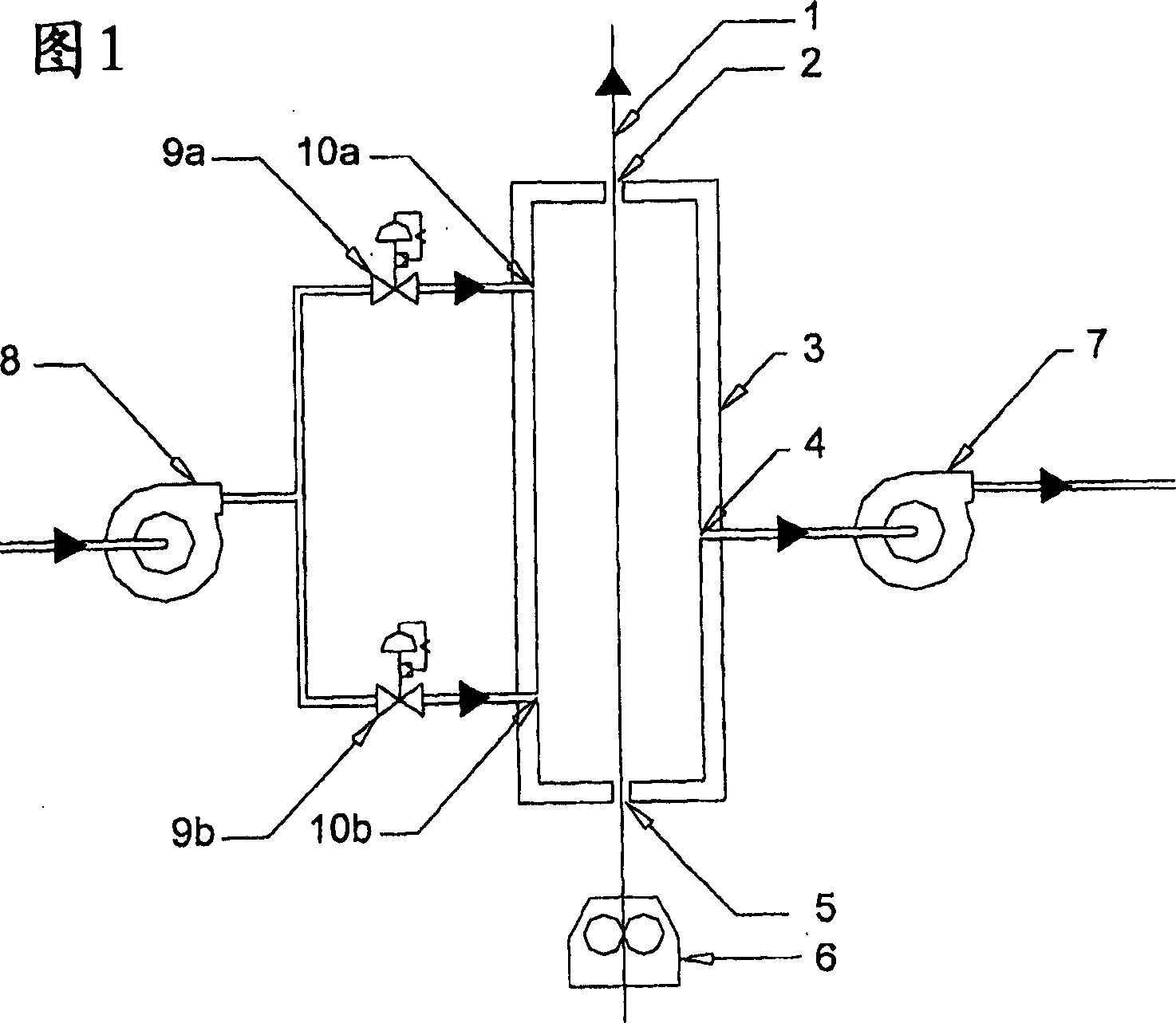
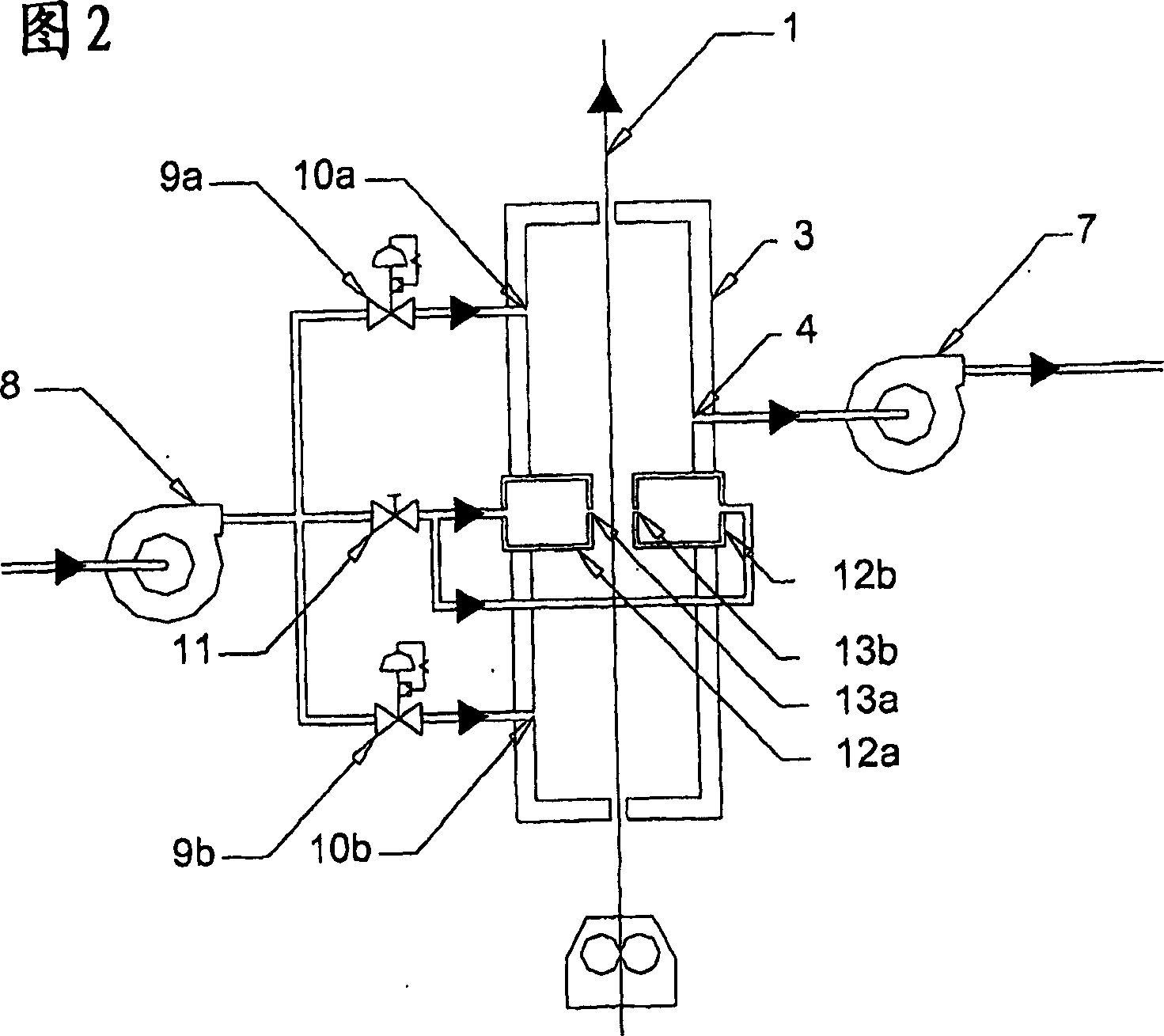
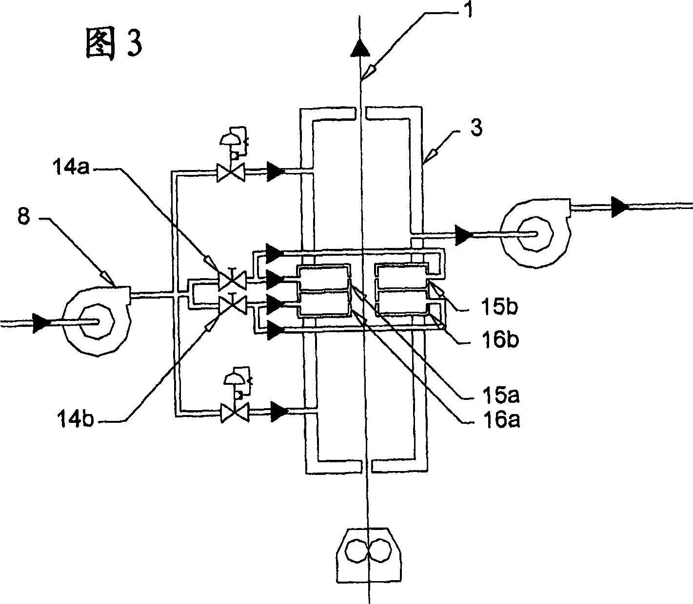
[0032] [32] Referring to Figure 1, there can be seen a vertical drying oven according to the prior art. Usually, a non-metallic cladding production line, in particular a production line for applying a paint layer on a steel strip, comprises a pretreatment zone of the steel strip surface, which is not shown in FIG. Followed by a machine 6 for applying a coating, in particular a liquid film of paint, to the steel strip 1 . Coverage is generally ensured by application with a roller.

[0033] [33] The steel strip 1 with its coating then enters a drying zone consisting of a furnace forming a channel 3 . The steel strip is threaded vertically into the furnace, as shown in FIG. 1 . Drying is achieved by keeping the steel strip 1 and the coating at the desired temperature at which the coating can be dried and baked. Advantageously, the heating of the steel strip 1 can be carried out by means of an electromagnetic induction system not shown in the figure.

[0034] [34] During the d...


PUM


Abstract

The invention relates to a method of drying a non-metallic coating on a steel band (1), whereby the steel band (1) is conveyed into a vertical drying furnace (3) with relatively cold walls. According to the invention, hot air is then injected into the upper part (10a) and the lower part (10b) of the furnace in order to prevent the condensation of vapours on the walls of the furnace, and the injected air is subsequently drawn off (4). A dynamic brake is produced by injecting (13a, 13b) hot air between the lower part and the upper part of the furnace at a distance from the inlet and the outlet thereof and by creating an overpressure condition in the tunnel of the drying furnace, such as to limit the entry of cold dead air and the chimney effect in the vertical furnace.

Description

technical field [0001] [01] The present invention relates to a method for drying a non-metallic coating on a steel strip, according to which the steel strip is introduced into a vertical drying furnace - the walls of which are relatively cool, hot air is passed through the drying furnace The lower and upper parts of the furnace are injected to avoid steam condensation on the furnace wall and to discharge the injected air. [0002] [02] The invention relates in particular to a method for drying a coating consisting of a paint layer. Background technique [0003] [03] The non-metallic coating of the steel strip is carried out using production equipment or production lines, which generally include a pretreatment zone for the surface of the steel strip, followed by a coating zone for applying a coating The liquid film is applied, in particular by means of a roller, followed by a drying zone for said liquid film. [0004] [04] Drying is accomplished by maintaining the scaffold ...

Claims


Application Information

Patent Timeline
IPC IPC(8): F26B13/10F26B21/00B05D3/02B05D3/04F26B13/00
CPCF26B13/005B05D2202/10F26B21/004B05D3/0413B05D3/0254F26B13/10
Inventor F·德龙萨尔P·迪阿梅尔
Owner STEIN-HEURTEY
Why Eureka
Try Eureka