Plane deslagging structure of die-casting die used for ultra-low-speed die-casting of camshaft front bearing cap

A die-casting die and camshaft technology, which is applied in the field of the die-casting die plane slag discharge structure of the ultra-low-speed die-casting camshaft front bearing cover, can solve the problem of reducing the probability of aluminum alloy solution encapsulating gas, prolonging the cooling process of exhaust time, and the cold gap. or loose points falling off, to make up for natural defects, provide product qualification rates, and reduce production costs

Inactive Publication Date: 2015-03-25
TAICANG HAIJIA VEHICLE FITTINGS
View PDF6 Cites 0 Cited by
  • Summary
  • Abstract
  • Description
  • Claims
  • Application Information

AI Technical Summary

Problems solved by technology

In order to improve the safety factor, the thickness of the camshaft structure was also appropriately increased while working on the material. However, the shrinkage cavity and porosity of the ultra-thick aluminum alloy die-casting parts have always been a problem that plagued the industry.
The use of low-speed die-casting can reduce the turbulent flow in the die-casting process, reduce the probability of aluminum alloy solution wrapping gas, prolong the exhaust time and the cooling process in the flow, and solve the shrinkage problem of ultra-thick die-casting parts, but for low-speed die-casting process , and a new contradiction is derived, that is, for some dead corners of the flow channel that cannot be satisfied by the low-speed process, such as sharp corners and narrow passages, there is a phenomenon that the material is too cold and cannot be sealed, so another defect type of die castings is produced—— — Cold insulation (or micro porosity)
Objectively speaking, the sharp angle on the camshaft structure does not reduce the strength of the product, but if the cold septum is right on the processing surface, due to the cutting force, the cold septum or loose point will fall off and affect the quality of the processed surface

Method used


Image

  • Plane deslagging structure of die-casting die used for ultra-low-speed die-casting of camshaft front bearing cap
  • Plane deslagging structure of die-casting die used for ultra-low-speed die-casting of camshaft front bearing cap
  • Plane deslagging structure of die-casting die used for ultra-low-speed die-casting of camshaft front bearing cap

Examples


Embodiment Construction

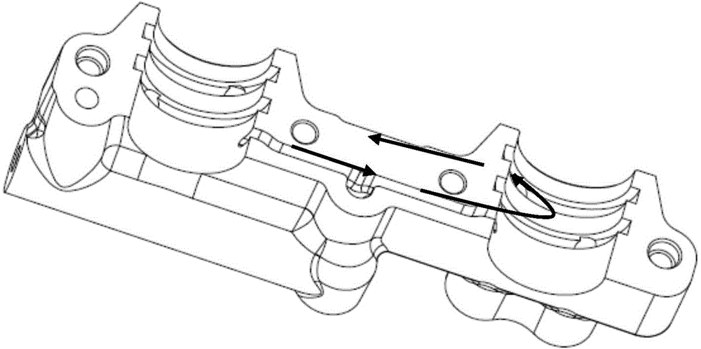
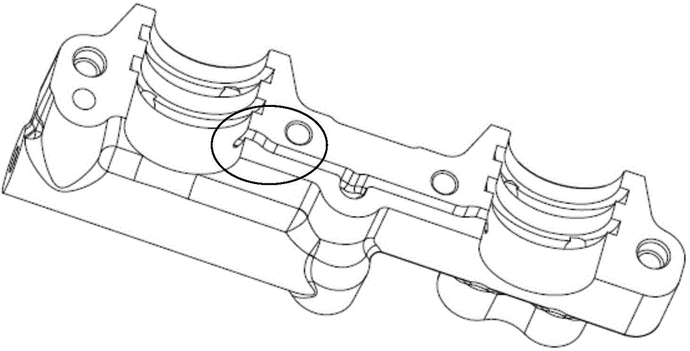
[0017] like figure 1 As shown, in the die-casting mold of the ultra-low speed die-casting camshaft front bearing cover, during die-casting, figure 1 It shows the flow direction of the aluminum liquid, specifically the flow direction of the aluminum liquid in the projected direction. The dead angle area in the mold is relatively independent. Under the action of the pressure difference of the aluminum liquid, it can only be filled when the aluminum liquid flows to the right according to the direction of the arrow in the figure. Only when the terminal backflow can take care of the dead corner area. The initial aluminum liquid does not fill the dead zone, leaving a gap, and the reflowed aluminum liquid replenishes. At this time, the temperature of the two aluminum liquids is different, and the joint area of ​​the two aluminum materials will form a cold gap area, such as figure 2 The circled area in .

[0018] like image 3 Shown, in the present invention, by counting the volum...


PUM


Abstract

The invention provides a plane deslagging structure of a die-casting die used for ultra-low-speed die-casting of a camshaft front bearing cap. Cold shut areas are arranged on the die-casting die, and slag accumulating holes are additionally formed in the positions corresponding to the cold shut areas and are used for collecting cold metal. According to the plane deslagging structure inside the die-casting die used for ultra-low-speed die-casting of the camshaft front bearing cap, by considering the actual flowing direction of molten aluminum in a die cavity in practice and the influence of temperature changing and gas discharging to products in production, the structure design of the die is improved, local modification is carried out on concave die cavities, the cold shut phenomenon in low-speed die-casting is reduced, local product quality is improved, and the rejection rate is lowered.

Description

technical field [0001] The invention relates to a plane slagging structure of an ultra-low-speed die-casting die, in particular to a plane slag-removing structure of a die-casting die for an ultra-low speed die-casting camshaft front bearing cover. Background technique [0002] The camshaft front bearing cover is a dual bearing positioning and protection device for the front transmission gear of the automobile. It is required to be stable and reliable in structure, not easy to deform, and can maintain good rigidity and dimensional stability even under high temperature conditions. Due to the needs of light weight and low-carbon consumption of automobiles, aluminum alloys are generally used to replace cast iron parts in cam bearing caps. In order to meet the requirements of rigidity, some other elements to improve performance are appropriately added to aluminum alloys, such as increasing the content of silicon. , the stability of silicon atoms reduces the mobility of aluminum ...

Claims


Application Information

Patent Timeline
Patent Type & Authority Applications(China)
IPC IPC(8): B22D17/22
CPCB22D17/22
Inventor 陈振延
Owner TAICANG HAIJIA VEHICLE FITTINGS
Why Eureka
Try Eureka