An exhaust structure in the die-casting mold of the front bearing cover of the ultra-low-speed die-cast camshaft

A technology for die-casting molds and camshafts, which is applied in the field of exhaust structures in die-casting molds. It can solve the problems of many appearance and internal defects, gas cannot be well removed, and the shape of the exhaust structure is single, so as to solve the phenomenon of air separation and improve Process difficulty and the effect of reducing scrap rate

Active Publication Date: 2016-08-31
苏州梅克卡斯汽车科技有限公司
View PDF7 Cites 0 Cited by
  • Summary
  • Abstract
  • Description
  • Claims
  • Application Information

AI Technical Summary

Problems solved by technology

The existing technologies mainly include the following two types: 1. Set up exhaust grooves on the parting surface. However, due to the large thickness of most products, when the die-casting process adopts ultra-low speed, the gas in the complex cavity cannot be well removed. , resulting in more appearance and internal defects and low pass rate when the product is cast
2. Ordinary insert exhaust, such an exhaust structure has a single shape, which cannot be fitted with the exhaust position that requires a specific position, so as to well exclude the gas at a specific point, resulting in air barrier defects

Method used


Image

  • An exhaust structure in the die-casting mold of the front bearing cover of the ultra-low-speed die-cast camshaft
  • An exhaust structure in the die-casting mold of the front bearing cover of the ultra-low-speed die-cast camshaft
  • An exhaust structure in the die-casting mold of the front bearing cover of the ultra-low-speed die-cast camshaft

Examples


Embodiment Construction

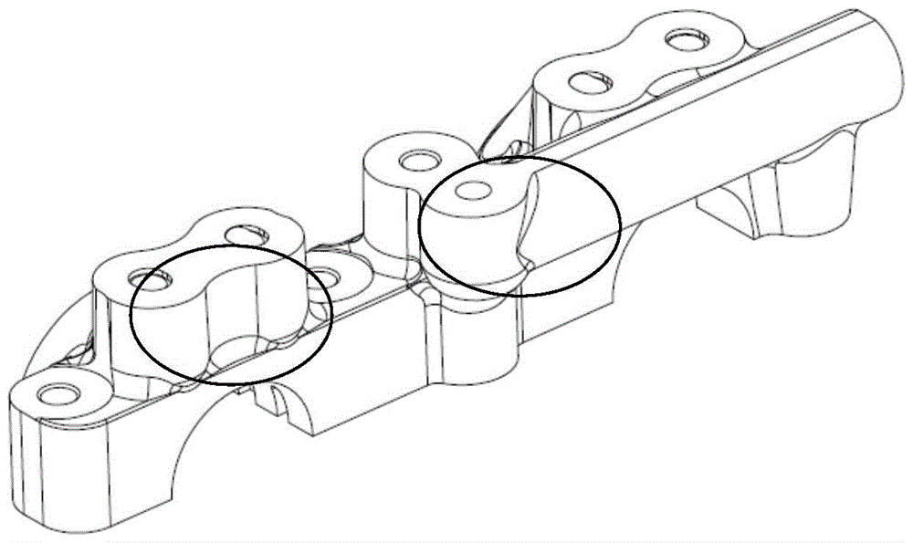
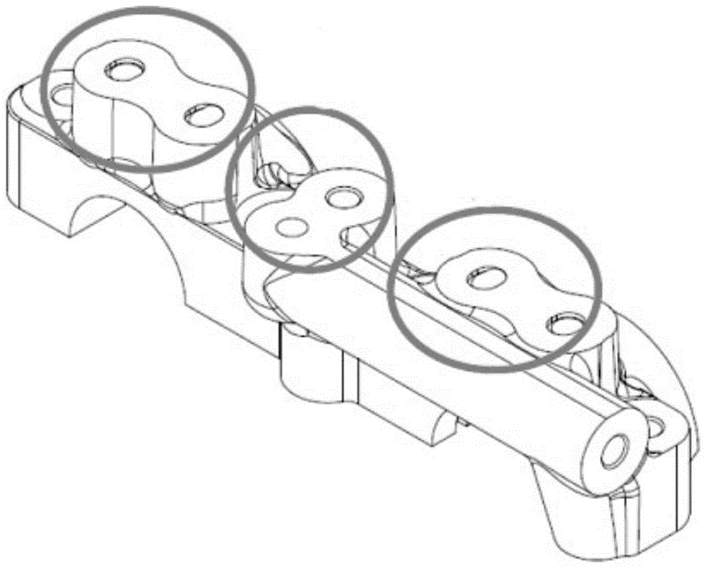
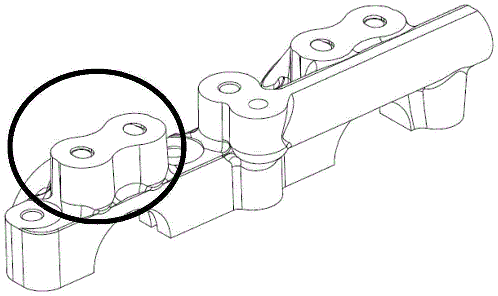
[0022] Such as figure 1 , 2 As shown, in the die-casting mold of the front bearing cap of the ultra-low-speed die-casting camshaft, the area circled in the figure is the cavity structure of the mold, where the flow rate of molten aluminum in low-speed die-casting is lower than that of high-speed die-casting, the aluminum liquid The impact on the surface of the cavity during the flow is too gentle, and some gas will accumulate in the dead corner. Due to the flow of aluminum liquid, the die casting will form an air barrier. Such an area is called a trapped air area. image 3 Shown is a gas barrier defect caused by the separation of molten aluminum caused by the gas barrier.

[0023] Such as Figure 4 , 5 As shown, because aluminum water is easy to drill into the exhaust channel and block the exhaust channel, it has always been a difficult point in the die-casting industry to set the exhaust gas on the mold cavity. After repeated experiments, the present invention has measured...


PUM


Abstract

The invention discloses an inner venting structure of a pressure casting die of a front bearing cap of an ultra-low speed pressure casting cam shaft. The pressure casting die is provided with an air trapping area, wherein the inner surface of the air trapping area is provided with a 8-shaped insert; the top of the 8-shaped insert is connected with a die top block; an air overflowing gap is formed between the bottom of the 8-shaped insert and the surface of an adjacent die and is communicated with an outer exhaust passage of the die. According to the inner venting structure of the pressure casting die of the front bearing cap of the ultra-low speed pressure casting cam shaft, the practical flow direction of molten aluminum in a die cavity and influence on a product by temperature change and air discharge during production are considered, the structural design of the die is improved, a pit mold cavity part is subjected to local transformation, a trap phenomenon in low-speed pressure casting is thoroughly eliminated, the local quality of the product is improved, and a rejection rate is lowered.

Description

technical field [0001] The invention relates to an exhaust structure of an ultra-low-speed die-casting mold, in particular to an exhaust structure in an ultra-low-speed die-cast camshaft front bearing cover in a die-casting mold. Background technique [0002] Shrinkage cavities and porosity of ultra-thick aluminum alloy die-casting parts have always been a difficult problem in the industry. The low-speed die-casting method reduces the turbulent flow in the die-casting process, reduces the probability of the aluminum alloy melt wrapping gas, prolongs the exhaust time and the cooling process in the flow, and can solve the shrinkage problem of ultra-thick die-casting parts, but Because the flow rate of molten aluminum in low-speed die-casting is lower than that in high-speed die-casting, the impact of molten aluminum on the surface of the cavity during the flow is too gentle, so some gas will accumulate in the dead corners, mainly in the deep pits formed as a whole, so the surf...

Claims


Application Information

Patent Timeline
Patent Type & Authority Patents(China)
IPC IPC(8): B22D17/22
CPCB22D17/22
Inventor 陈振延
Owner 苏州梅克卡斯汽车科技有限公司
Why Eureka
Try Eureka