
Instrument panel beam drilling device

A drilling device and instrument panel technology, which is applied in positioning devices, drilling/drilling equipment, portable drilling rigs, etc., can solve the problems of low processing efficiency, troublesome processing of instrument panel crossbeam holes, poor processing quality, etc., and achieve the goal of drilling Fast hole speed, improved hole processing speed, and high drilling accuracy

Active Publication Date: 2016-09-14
扬州市明创新型建材科技有限公司
View PDF5 Cites 1 Cited by
  • Summary
  • Abstract
  • Description
  • Claims
  • Application Information

AI Technical Summary

Problems solved by technology

[0003] In view of the above-mentioned deficiencies existing in the prior art, the object of the present invention is how to solve the problems of troublesome processing, low processing efficiency, and poor processing quality of existing instrument panel beams, and provide an instrument panel beam drilling device that can quickly improve the Process efficiency and improve product quality

Method used


Image

  • Instrument panel beam drilling device
  • Instrument panel beam drilling device
  • Instrument panel beam drilling device

Examples


Embodiment

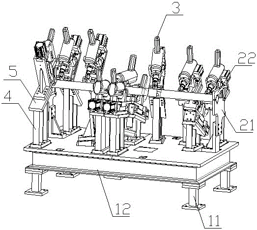
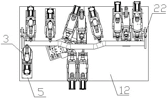
[0014] Example: see figure 2 , image 3 , an instrument panel beam drilling device, comprising a base, a positioning mechanism and a drilling device.

[0015] The base includes pillars 11 and a platform 12 . The positioning mechanism includes a support plate 21 and a pressing plate 22 arranged at both ends of the base. During specific implementation, the supporting plate 21 is fixed above the table top and close to the two ends of the table top 22, and one end of the pressing plate 22 rotates with one side of the support plate 21. The other end is connected to the other side of the support plate 21 through a locking structure; there is a V-shaped slot on the upper part of the support plate 21, and an inverted V-shaped slot is provided on the lower part of the pressure plate 22. Through the support plate 21 and the pressure plate 22 The cooperation can tighten the instrument panel beam. In actual production, a positioning block is provided in the slot of the support plate 2...


PUM


Abstract

The invention discloses an instrument panel transverse beam hole drilling device. The instrument panel transverse beam hole drilling device comprises a base, a positioning mechanism and a hole drilling device. The base comprises supporting columns and a table top. The positioning mechanism comprises supporting plates and pressing plates, wherein the supporting plates and the pressing plates are arranged at the two ends of the base. V-shaped clamping grooves are formed in the upper portions of the supporting plates, and inverted-V-shaped clamping grooves are correspondingly formed in the lower portions of the pressing plates. The hole drilling device comprises a plurality of electric hand drills, the electric hand drills are installed on the base through the supports, each support is provided with an electric drill installation plate, and the electric hand drills are installed on the electric drill installation plates in a sliding-fit mode. The instrument panel transverse beam hole drilling device is simple in structure and convenient to use, the machining efficiency can be rapidly improved, and the product quality can be improved.

Description

technical field [0001] The invention relates to a processing equipment for auto parts, in particular to a drilling device for an instrument panel beam. Background technique [0002] The instrument panel crossbeam is the internal skeleton of the instrument panel system, and is the connection bracket between the instrument panel system and the body assembly. It supports the instrument panel system, provides the installation of components in the instrument panel system, and increases the strength of the vehicle body. like figure 1 As shown, it is a tubular structure as a whole, with clamping holes (assembly holes) processed on both sides and bottom of the instrument panel beam, usually a total of 12, but due to the irregular shape of the instrument panel beam, it is usually lower at both ends and in the middle It is high and has a certain twisted structure, so it is very troublesome in the process of card control processing. In the existing processing method, multi-sequence is...

Claims


Application Information

Patent Timeline
Patent Type & Authority Patents(China)
IPC IPC(8): B23Q1/03B23Q3/06B23B45/02
CPCB23B45/003B23B45/02B25H1/0021
Inventor 唐舜清罗先斌
Owner 扬州市明创新型建材科技有限公司
Learn More