Workpiece clamping mechanism

A clamping mechanism and workpiece clamping technology, which is applied in the direction of manufacturing tools, electric processing equipment, metal processing equipment, etc., can solve the problems of high work intensity, affecting processing efficiency, and cannot be fixed, and achieve high repositioning accuracy, simple structure, Strong clamping effect

Inactive Publication Date: 2015-03-25
CHENGDU HONGSHAN TECH
View PDF6 Cites 5 Cited by
  • Summary
  • Abstract
  • Description
  • Claims
  • Application Information

AI Technical Summary

Problems solved by technology

However, the existing fixtures cannot meet the above requirements at the same time: although some can be clamped firmly, after each workpiece is clamped, repeated side alignment and centering operations are required, which not only increases the work intensity, but also affects the processing efficie

Method used


Image

  • Workpiece clamping mechanism
  • Workpiece clamping mechanism

Examples


Example Embodiment

[0014] Example 1:

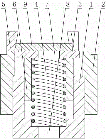
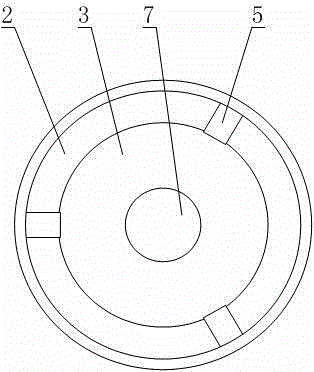
[0015] Such as Figure 1 to Figure 2 As shown, the workpiece clamping mechanism includes a supporting plate 3, an elastic member 4, a supporting cylinder 1 with an upper opening and a lower end closed, and a positioning cylinder 2 coaxially arranged with the supporting cylinder 1 and opening at both upper and lower ends; the supporting plate 3 is located on the supporting cylinder Above 1, the support plate 3 is provided with a first port 7, the center line of the first port 7 overlaps the axis of the support cylinder 1, and the upper and lower ends of the elastic member 4 are respectively connected to the lower end surface of the support plate 3 and the support cylinder The bottom of the inner wall of 1 is fixedly connected, the positioning cylinder 2 is sleeved outside the support cylinder 1, and the upper end of the positioning cylinder 2 is provided with a plurality of clamping jaws 5 for positioning the apex of the workpiece. The inner side of the clampin...

Example Embodiment

[0018] Example 2

[0019] This embodiment further defines the following on the basis of embodiment 1: The lower end surface of the support plate 3 is fixedly connected with a limit cylinder 6 which is guided by the support plate 3 and is arranged coaxially with the support cylinder 1. The limit cylinder 6 The lower end is located in the support tube 1. In this embodiment, the upper end of the elastic member 4 may be located in the limiting cylinder 6. In order to achieve a good and stable guiding function, the outer wall of the limit cylinder 6 and the inner wall of the support cylinder 1 should be as close as possible, and the limit cylinder 6 should also be able to move up and down relative to the support cylinder 1.

Example Embodiment

[0020] Example 3

[0021] This embodiment further defines the following on the basis of the first embodiment: the positioning cylinder 2 and the supporting cylinder 1 are screwed together. In this embodiment, the inner wall of the positioning cylinder 2 may be provided with internal threads, the outer wall of the support cylinder 1 may be provided with external threads matching the internal threads, and the positioning cylinder 2 is sleeved on the support cylinder 1 through the threads. In application, if the thickness of the workpiece is large, the positioning cylinder 2 can be rotated to move upward relative to the supporting cylinder 1; if the thickness of the workpiece is small, the operation is the opposite.


PUM


Abstract

The invention discloses a workpiece clamping mechanism which comprises a supporting plate, an elastic piece, a supporting barrel and a locating barrel. The upper end of the supporting barrel is open, the lower end of the supporting barrel is closed, the locating barrel and the supporting barrel are arranged coaxially, and the upper end and the lower end of the locating barrel are open. The supporting plate is located above the supporting barrel, a first through opening is formed in the supporting plate, the center line of the first through opening and the axis of the supporting barrel are overlapped, the upper end and the lower end of the elastic piece are fixedly connected with the lower end face of the supporting plate and the bottom of the inner wall of the supporting barrel respectively, the supporting barrel is sleeved with the locating barrel, a plurality of clamping jaws used for locating top points of workpieces are arranged at the upper end of the locating barrel, and the inner side faces of the clamping jaws are gradually inclined towards the axis of the locating barrel from bottom to top. The workpiece clamping mechanism has the advantages that clamping is convenient and firm, relocating precision is high, good universality is achieved, and the structure is simple.

Description

technical field [0001] The invention relates to the field of electric discharge machining, in particular to a workpiece clamping mechanism. Background technique [0002] EDM is based on the electro-corrosion phenomenon generated when the pulse discharge between the two electrodes is used to remove material. In order to ensure the processing quality, fixtures are required to position and fix the workpiece during EDM, so as to avoid the position deviation of the workpiece when it is impacted by the working fluid or disturbed by the outside world. This requires that the fixture can not only be firmly clamped and positioned accurately, but also be easy to assemble and disassemble. However, the existing fixtures cannot meet the above requirements at the same time: although some can be clamped firmly, after each workpiece is clamped, repeated side alignment and centering operations are required, which not only increases the work intensity, but also affects the processing efficien...

Claims


Application Information

Patent Timeline
IPC IPC(8): B23H11/00B23H1/00
CPCB23H11/003B23H1/00
Inventor 曾维亮
Owner CHENGDU HONGSHAN TECH
Why Eureka
Try Eureka