Ink cavity structure of an inkjet printer nozzle

A technology of inkjet printers and nozzles, which is applied in printing and other directions, and can solve problems such as mutual interference, inability to adjust the volume of ink chambers, and narrow variation range of ink droplet volume.

Active Publication Date: 2016-05-04
AMSKY TECHNOLOGY CO LTD
View PDF7 Cites 2 Cited by
  • Summary
  • Abstract
  • Description
  • Claims
  • Application Information

AI Technical Summary

Problems solved by technology

The size of the ejected ink drop (that is, the amount of ink drop) is affected by parameters such as piezoelectric ceramic deformation, voltage, and ink chamber volume. Once the structure of the nozzle is finalized, the ink chamber volume cannot be adjusted, and the ink drop volume is only controlled by the voltage waveform. , in this case, the variation range of ink drop volume is relatively narrow
There is also the practice of directly cutting small grooves on the piezoelectric ceramic block to form ink chambers. This kind of ink chamber can make the two side walls have working piezoelectric ceramics, but this structure has a common pressure due to the adjacent ink chambers. Electric ceramics, which makes it necessary for the adjacent ink chambers not to work at the same time when the nozzle is working, otherwise it will interfere with each other

Method used


Image

  • Ink cavity structure of an inkjet printer nozzle
  • Ink cavity structure of an inkjet printer nozzle
  • Ink cavity structure of an inkjet printer nozzle

Examples


Embodiment 1

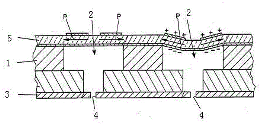
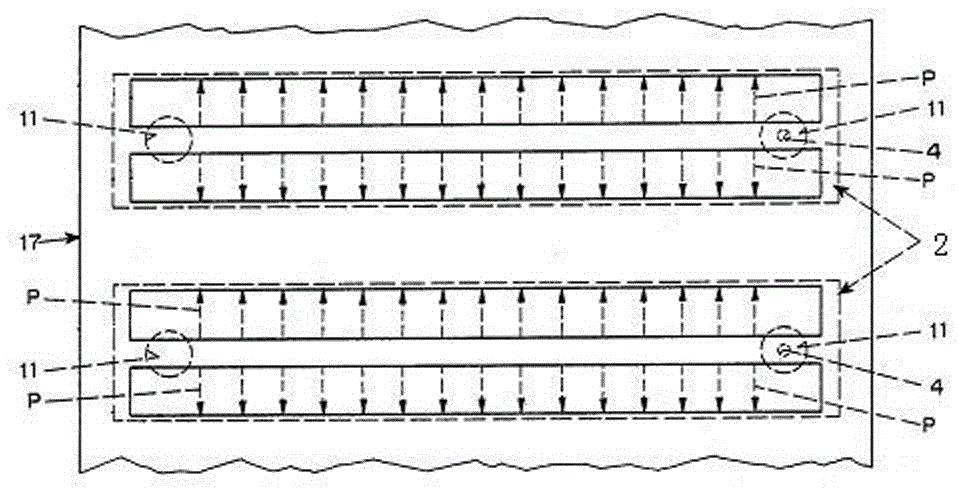
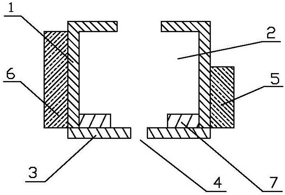
[0018] Figure 5 It is a cross-sectional view of the ink chamber as a single pressure chamber, and the arrow is the ink flow direction in the figure. As shown in the figure, the present invention includes an orifice plate 3, an orifice lining plate 7, an ink chamber plate 12, piezoelectric ceramics 5, piezoelectric The ceramic 6, the flexible circuit board 8, the flexible circuit board 9, and the ink inlet plate 10 are assembled by stacking them. Have the ink inlet hole 11 on the ink inlet plate 10, have the ink chamber 2 on the ink chamber plate 12 (this ink chamber 2 is actually surrounded by the hole here and the flexible circuit board of the ink chamber plate to form), the spray hole There are ink outlet holes 71 on the backing plate 7, and nozzle holes 4 for ejecting ink droplets are opened on the orifice plate 3, and the ink chamber and these holes form a pressure chamber. There is also a groove 71 on the nozzle liner 7, and a groove 101 on the ink inlet plate 10, and p...

Embodiment 2

[0020] Image 6 It is a cross-sectional view of the ink chamber as a double pressure chamber. This embodiment is similar to Embodiment 1, except that there are 3 ink chamber plates, namely ink chamber plates 13, 14, and 15. These 3 ink chamber plates separate the ink chamber, There are two pressure chambers, namely pressure chamber 21 and pressure chamber 22, and a piece of piezoelectric ceramic is arranged on each pressure chamber. The two pressure chambers are divided into one large and one small by volume, the large piezoelectric ceramic 6 is installed on the side of the large pressure chamber 21, and the small piezoelectric ceramic 5 is installed on the side of the small pressure chamber 22. In this embodiment, the piezoelectric ceramic is PZT5, the width of the large piezoelectric ceramic 6 is 10 millimeters, the width of the small piezoelectric ceramic 5 is 5 millimeters, the voltage is 60-100 V, and the volume of the large pressure chamber 21 is 0.6 cubic millimeters. ...


PUM


Abstract

The invention discloses an ink cavity structure of a sprayer of an ink-jet printer. Spray holes used for spraying ink droplets out are formed in the sprayer. At least two ink cavities are formed in the sprayer, and two independently-controlled piezoelectric ceramic pieces are mounted on the wall of each ink cavity. According to the technical scheme, due to the fact that the structure that one ink cavity is provided with the two independently-controlled piezoelectric ceramic pieces is adopted, the changing range of the sizes of sprayed ink droplets is larger.

Description

technical field [0001] The invention belongs to the technical field of ink-jet printing, and in particular relates to an ink cavity of a nozzle for ink-jet printing using piezoelectric ceramics. Background technique [0002] The nozzles of inkjet printers are equipped with nozzle holes and ink chambers. The number of nozzle holes and ink chambers is generally set according to needs. One ink chamber corresponds to one or more nozzle holes. In the technology of inkjet printing using piezoelectric ceramic technology Field, the wall of each ink chamber on the nozzle is equipped with piezoelectric ceramics, and the piezoelectric ceramics are deformed by applying a pulse voltage to the piezoelectric ceramics, so that the ink chambers are deformed, and the resulting deformation pressure makes the ink droplets ejected . figure 1 , 2 It shows the general structure of the nozzle ink chamber of the current piezoelectric ceramic technology. The lower part of the nozzle is the orifice ...

Claims


Application Information

Patent Timeline
Patent Type & Authority Patents(China)
IPC IPC(8): B41J2/175
Inventor 周勇李兵涛
Owner AMSKY TECHNOLOGY CO LTD
Why Eureka
Try Eureka