
Derrick head and derrick device

A technology of a pole holding head and an installation part, which is applied to the field of pole holding head and pole holding device, can solve the problem of large eccentric force of pole holding device, etc., and achieve the effects of ensuring stability, sensitive rotation action, and simple and reliable operation.

Active Publication Date: 2015-03-25
STATE GRID CORP OF CHINA +1
View PDF10 Cites 0 Cited by
  • Summary
  • Abstract
  • Description
  • Claims
  • Application Information

AI Technical Summary

Problems solved by technology

[0007] In view of this, the embodiment of the present invention provides a pole-holding head and a pole-holding device, the main purpose of which is to solve the problem of excessive eccentric force on the pole-holding device when lifting iron tower components, and to ensure the overall stability and stability of the pole-holding device. construction safety

Method used


Image

  • Derrick head and derrick device
  • Derrick head and derrick device
  • Derrick head and derrick device

Examples


Embodiment Construction

[0051] The present invention will be further described in detail below in conjunction with the accompanying drawings and embodiments.

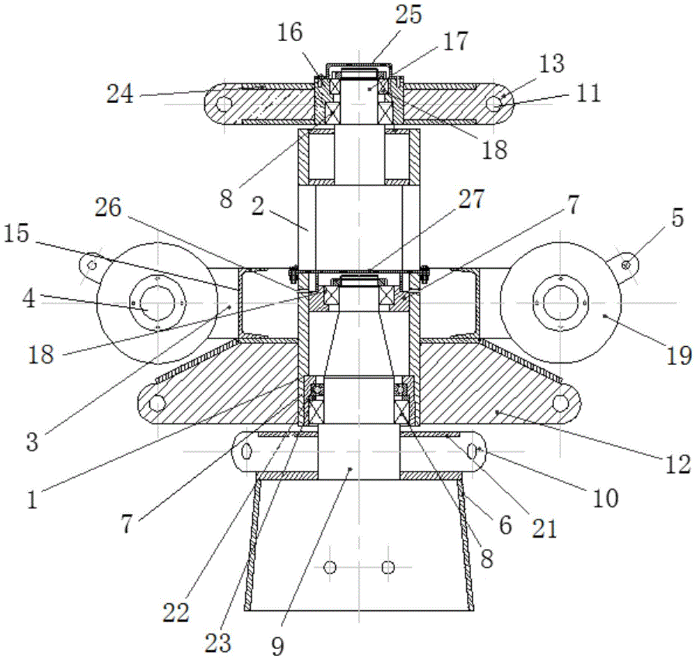
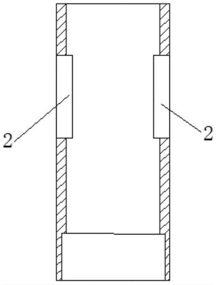
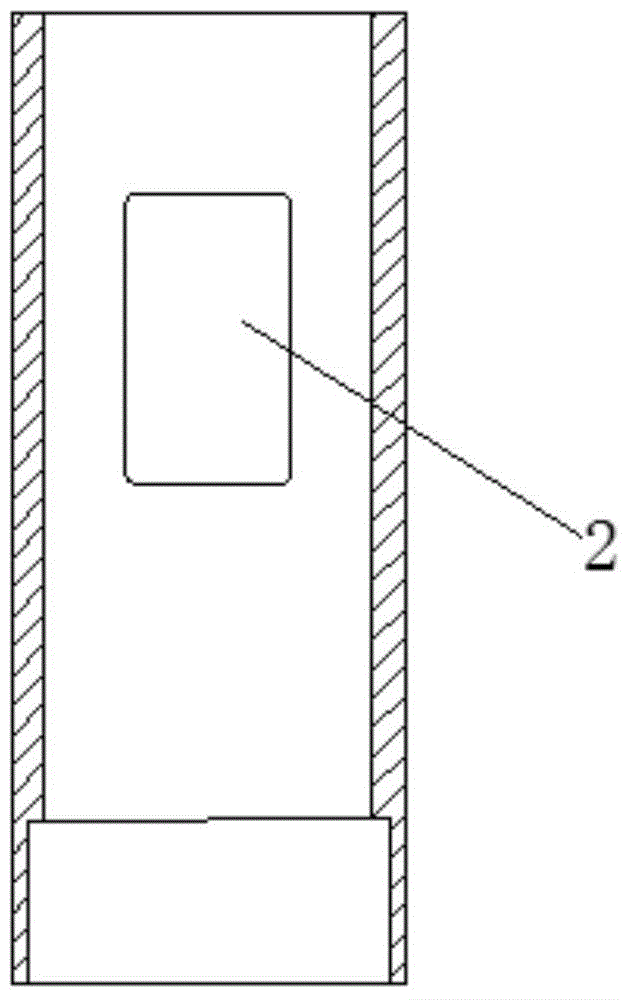
[0052] like figure 1 As shown, the embodiment of the present invention provides a pole holding head, which includes a column 1 and a pulley block supporting frame 3 . Specifically, such as Figure 2-1, as shown in 2-2, the column 1 is a hollow structure, which is used to be installed on the upper end of the rod body of the pole holding device, and its outer wall is provided with two passing holes 2 oppositely arranged, and the connecting line of the two passing holes 2 passes through the side of the column 1 center and on the same level. There are two pulley block support frames 3, which are respectively installed on the outer wall of the column 1 below the two passing holes 2. The end of the pulley block support frame 3 is provided with a pulley assembly installation part 4 for installing the pulley assembly 19.

[0053] The pole-holding h...


PUM


Abstract

The invention discloses a derrick head and a derrick device and relates to the technical field of engineering machines. The derrick head and the derrick device aim at solving the problem that eccentric force on a derrick is too large when an iron tower component is lifted and ensuring the stability and the construction safety of the overall derrick. According to the main technical scheme, the derrick head comprises a stand column and pulley set supporting frames, the stand column is of a hollow structure and is installed at the upper end of a derrick body, two through holes which are arranged oppositely are formed in the outer wall of the stand column, the connecting line of the two through holes penetrates through the center of the stand column, and the two through holes are formed in the same horizontal plane. The two pulley set supporting frames are installed on the parts, below the through holes, of the outer wall of the stand column, and pulley assembly installation parts are arranged at the tail ends of the pulley set supporting frames. The invention further discloses the derrick device which comprises the derrick body and the derrick head, and the derrick head is arranged at the top end of the derrick body. The derrick head and the derrick device are mainly used for erecting of high-voltage iron towers and the like in the electric transmission line construction, and stability and the construction safety are good.

Description

technical field [0001] The invention relates to the technical field of engineering machinery, in particular to a pole holding head and a pole holding device. Background technique [0002] In the construction of transmission lines, it is often necessary to erect high-voltage iron towers, etc., and high-voltage iron towers are generally quadrangular iron towers assembled from several steel rods as tower materials. When erecting a high-voltage iron frame, it is necessary to first build the foundation and tower feet on the ground, and then gradually build up the tower material components. When the high-voltage iron tower is erected to a certain height, in order to safely transport each component to the erected height, it is necessary to use a pole The device (that is, the pole) is used as an auxiliary lifting tool. [0003] The existing pole holding devices generally include a pole body and a pole holding head. The main body of the pole body is a structure composed of angle ste...

Claims


Application Information

Patent Timeline
Patent Type & Authority Applications(China)
IPC IPC(8): E04H12/34
CPCE04H12/342
Inventor 马增茂刘靖国程金梁王海波唐志海宋岷山田文敏
Owner STATE GRID CORP OF CHINA
Learn More