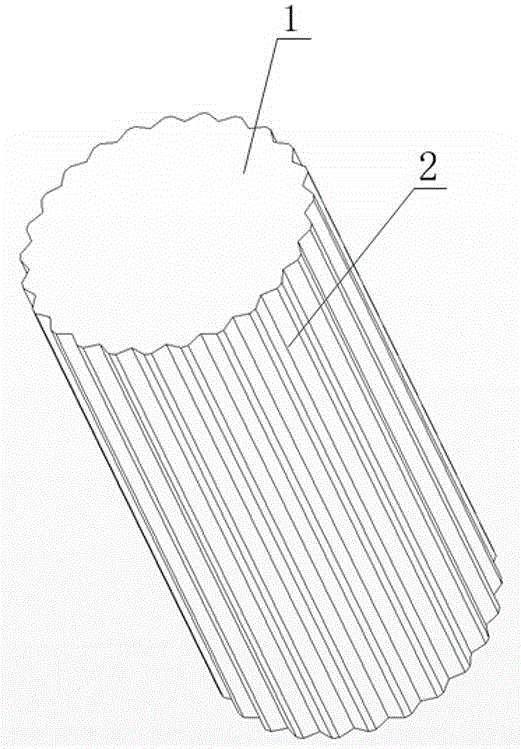
Buoyancy block surface structure for reducing ocean current resistance borne by waterproof pipe column
A technology of surface structure and buoyancy block, applied in the direction of drill pipe, casing, fluid flow, etc., can solve the problems of unfavorable compactness of self-weight structure, additional addition, etc., to reduce vortex-induced vibration, reduce the reaction force of connecting support, and reduce The effect of small ocean current resistance
- Summary
- Abstract
- Description
- Claims
- Application Information
AI Technical Summary
Problems solved by technology
Method used
Image

Examples
Embodiment 1
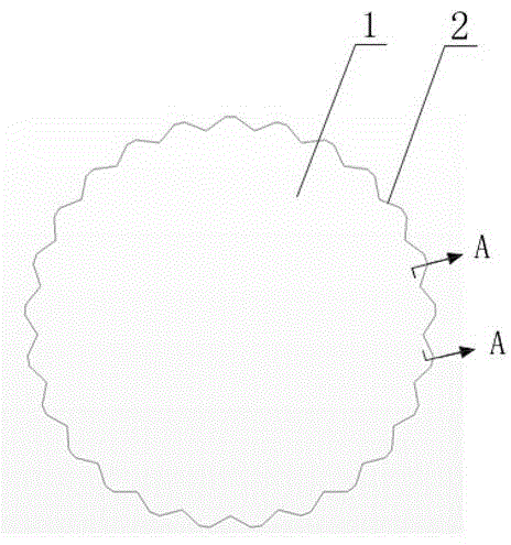
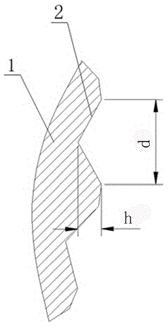
[0044] according to image 3 , the surface structure of the buoyancy block 1 is a triangular groove; the outer diameter D of the buoyancy block 1 is taken as 1m, here the outer contour of the buoyancy block 1 attached to the riser string is approximately a cylindrical surface, the groove width d=0.007Dmm, the groove Groove depth h=0.005D=5mm; under the Reynolds number Re=40000, carry out water tunnel numerical simulation on the smooth structure and the buoyancy block 1 under this triangular structure, and track the pressure difference resistance coefficient, and intercept the stable A piece of data is made into a line chart; Figure 16 is the line diagram of pressure differential resistance coefficient Cd under smooth structure, Figure 17 It is a broken line diagram of the pressure difference resistance coefficient Cd under the triangular groove structure, and the average value is respectively calculated as Cd=1.141 under the smooth surface, and Cd=0.827 under the triangular...
Embodiment 2
[0046] according to Figure 4 , the surface structure of the buoyancy block 1 is an arc-shaped groove; the outer diameter D of the buoyancy block 1 is taken as 1m, and the outer contour of the buoyancy block 1 attached to the riser string is approximated as a cylindrical surface, and the groove width d=0.07D =70mm, groove depth h=0.01D=10mm; carry out water tunnel numerical simulation on the buoyancy block 1 of this structure under the Reynolds number Re=40000; same as Example 1, obtain the pressure difference resistance coefficient Cd under this arc-shaped structure line chart, such as Figure 18 , find the average value of Cd=0.872 under the circular arc groove structure, so the pressure difference resistance coefficient Cd of this circular arc groove structure is 23.5% lower than that of the smooth surface structure.
Embodiment 3
[0048] according to Figure 13 , the surface structure of the buoyancy block 1 is a diamond-shaped distribution of circular pits; the outer diameter D of the buoyancy block 1 is 1m, and the outer contour of the buoyancy block 1 attached to the riser string is approximated as a cylindrical surface, and the width of the pits is d=0.1D=100mm, groove depth h=0.0.01D=10mm, distance s=0.003D=3mm between two dimples along the axis direction; numerical simulation of water tunnel is carried out at Reynolds number Re=40000, same as the embodiment 1. Obtain the broken line diagram of the pressure difference resistance coefficient Cd under the circular pit structure with diamond distribution, as shown in Figure 19 , find the average value of Cd=0.928 under the circular dimple structure with rhombus distribution, then, the pressure difference resistance coefficient Cd of the circular dimple structure with rhombus distribution is 18.7% lower than that of the smooth surface structure.
PUM
| Property | Measurement | Unit |
|---|---|---|
| Outer diameter | aaaaa | aaaaa |
| Width | aaaaa | aaaaa |
Abstract
Description
Claims
Application Information
 - R&D
- Intellectual Property
- Life Sciences
- Materials
- Tech Scout
- Unparalleled Data Quality
- Higher Quality Content
- 60% Fewer Hallucinations
Browse by: Latest US Patents, China's latest patents, Technical Efficacy Thesaurus, Application Domain, Technology Topic, Popular Technical Reports.
© 2025 PatSnap. All rights reserved.Legal|Privacy policy|Modern Slavery Act Transparency Statement|Sitemap|About US| Contact US: help@patsnap.com