A method and device for judging the position of a measuring and adjusting instrument in a downhole

A technology for judging devices and instruments, which is applied in the direction of construction, etc., can solve the problems of not being able to judge when the measuring and adjusting instrument leaves the water distributor, restricting the development of fine water injection technology in oil fields, and being unable to know the exact position of the measuring and adjusting instrument, so as to improve the efficiency of measuring and adjusting , improve oil recovery, and avoid mismeasurement and adjustment operations

Active Publication Date: 2017-07-11
贵州航天凯山石油仪器有限公司
View PDF5 Cites 0 Cited by
  • Summary
  • Abstract
  • Description
  • Claims
  • Application Information

AI Technical Summary

Problems solved by technology

The positioning steps on the existing water distributor can only limit the position in one direction, and cannot judge when the measuring and adjusting instrument leaves the water distributor when it moves in the reverse direction
Affected by the elastic deformation of the cable, in the absence of other identification features, it is impossible to know the exact position of the measuring and adjusting instrument after leaving the water distributor without knowing the encoder reading when the instrument has just left the water distributor, and the depth test error is relatively large
When the distance between adjacent layers is small, it is easy to make mistakes in the stop position, and it is easy to make wrong adjustments and tests on other layers.
Therefore, the interlayer spacing is generally more than 20 meters at present, which cannot be further reduced, which limits the development of oilfield fine water injection technology and cannot meet the needs of oilfield work

Method used


Image

  • A method and device for judging the position of a measuring and adjusting instrument in a downhole

Examples


Embodiment

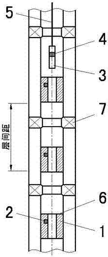
[0020] In specific implementation, such as figure 1 As shown, a permanent magnet 2 is installed at an appropriate position of the water distributor 1 to provide a specific magnetic signal source as a water distributor identification. A magnetic detection component 4 (such as a Hall device) is installed at a corresponding position in the measuring and adjusting instrument 3, and when the magnetic detection component is closest to the permanent magnet, the identification signal can be measured. When the measuring and adjusting instrument leaves the water distributor, the identification signal disappears rapidly. Because the number of water distributors in the well is known, according to the sequence of the detected identification signals, combined with the ground counter of the cable length (the length of the cable when it just left the water distributor is known), the location of the measuring and adjusting instrument can be accurately controlled. For example: in the process o...


PUM


Abstract

The invention discloses a method and device for judging the position of a test and regulation instrument in a pit. The method comprises the following steps: a set of permanent magnets are mounted on each water distributor in the pit, and meanwhile, a magnetic detection assembly is mounted on the test and regulation instrument; when the test and regulation instrument enters the signal range of the permanent magnets, a signal is fed back to the ground through the magnetic detection assembly on the test and regulation instrument, and then an operator on the ground can accurately know the accurate position of the test and regulation instrument in the pit. The device is simple in structure, low in cost and convenient to operate; when the water distributor is tested and regulated, the positioning precision is high, a packer in the pit cannot be mistakenly identified as the water distributor, the test and regulation instrument can be accurately positioned in the position of the water distributor needed to be tested and regulated in one time, and the error test and regulation operation is avoided; the test and regulation efficiency of the water distributor in the pit is greatly improved; the existing interlayer spacing of more than 20 meters can be reduced to be about 5 meters, the waterflooding displacement effect can be improved, and the raw oil recovery rate can be increased; favorable conditions are created for development of a fine separate zone waterflooding technology for an oil field.

Description

technical field [0001] The invention relates to a method and a device for judging the downhole position of a surveying and adjusting instrument, belonging to the technical field of downhole surveying and adjusting. Background technique [0002] When carrying out stratified flow testing and adjustment in the oil field, it is necessary to lower the measuring and adjusting instrument into the well with a cable, and ensure that the measuring and adjusting instrument is located at the specified height above the layer to be measured and adjusted. The positioning step on the existing water distributor can only limit the position in one direction, and it cannot be judged when the measuring and adjusting instrument will leave the water distributor when it moves in the reverse direction. Affected by the elastic deformation of the cable, without other identification features, it is impossible to know the exact position of the measuring and adjusting instrument after leaving the water d...

Claims


Application Information

Patent Timeline
Patent Type & Authority Patents(China)
IPC IPC(8): E21B47/092
CPCE21B47/092
Inventor 庞云伟魏炎红
Owner 贵州航天凯山石油仪器有限公司
Why Eureka
Try Eureka