Hydraulic electromagnetic directional valve

An electromagnetic reversing valve and hydraulic technology, which is applied in the field of electromagnetic valves, can solve problems such as armature jamming, and achieve the effects of reducing back pressure, moving lightly and flexibly, and being easy to move

Active Publication Date: 2015-03-25
JIANGXI WEIXIN HI-TECH OIL PRESSURE TECH CO LTD
View PDF7 Cites 1 Cited by
  • Summary
  • Abstract
  • Description
  • Claims
  • Application Information

AI Technical Summary

Problems solved by technology

[0003] The purpose of the present invention is to overcome the deficiencies of the prior art, adapt to the actual needs, and provide a hydraulic electromagnetic reversing valve to solve the technical problem that the armature in the current hydraulic reversing valve is stuck during work.

Method used


Image

  • Hydraulic electromagnetic directional valve
  • Hydraulic electromagnetic directional valve
  • Hydraulic electromagnetic directional valve

Examples


Embodiment 1

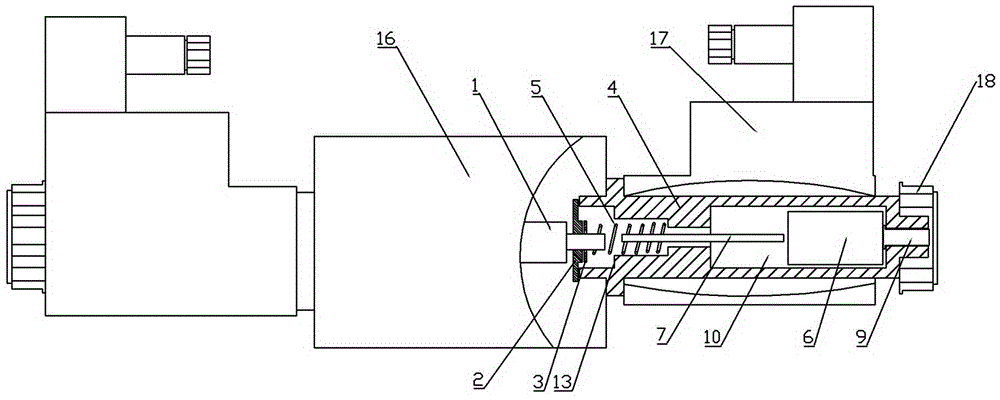
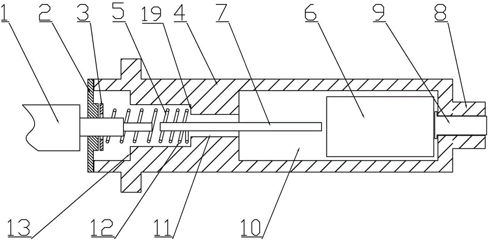
[0025] Embodiment 1: A hydraulic electromagnetic reversing valve, see figure 1 , figure 2 , image 3 It includes a valve body 16, a valve core 1 correspondingly arranged in the valve body, a magnetic sleeve 4 correspondingly connected with the valve body 16, and an armature 6 and a push rod correspondingly arranged in the inner cavity 10 of the magnetic sleeve 4 7. A reaction force spring 5 is also provided in the magnetic sleeve 4, and a limit step 19 is also correspondingly provided in the magnetic sleeve 4. One end of the reaction force spring 5 is in corresponding contact with the limit step 19, and the other One end is in corresponding contact with the magnetic core 1 via the magnetic core limiting piece 2 ; the diameter of the magnetic core limiting piece 2 is the same as the outer diameter of the end of the magnetic sleeve 4 . At the same time, a gasket 3 is also arranged between the magnetic core limiting piece 2 and the reaction force spring 5, and the magnetic cor...

Embodiment 2

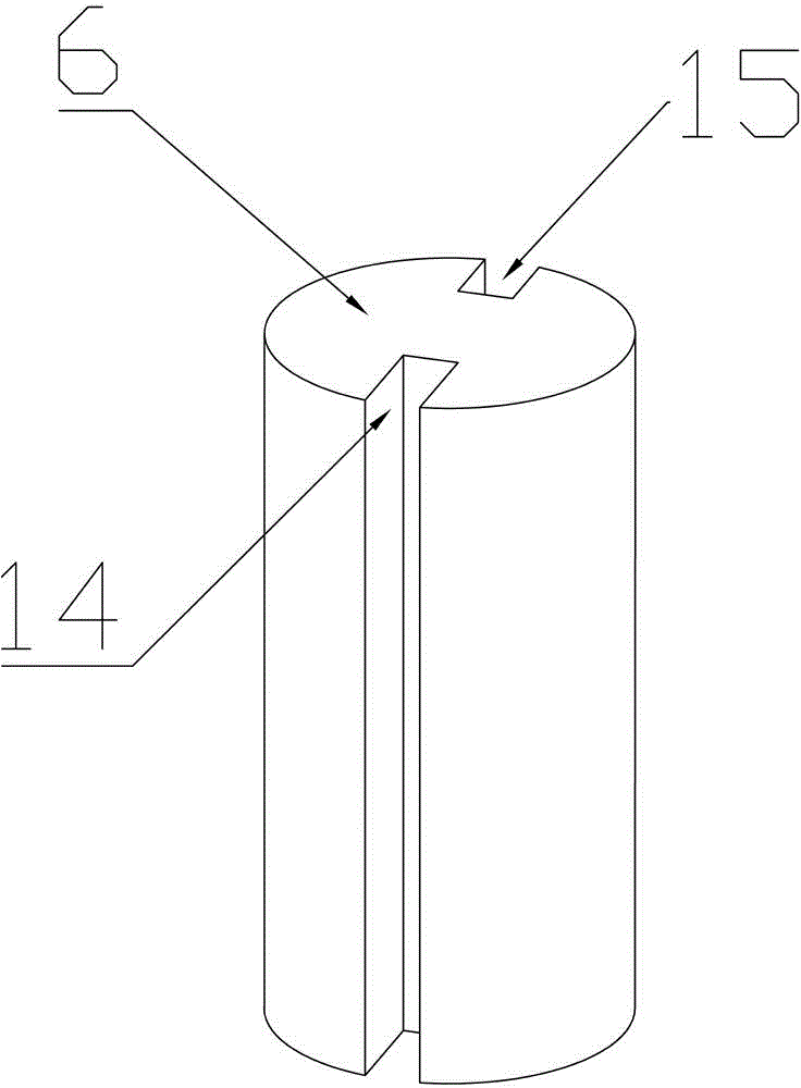
[0026] Example 2, such as Figure 1 to Figure 4 As shown, the similarities with Embodiment 1 will not be repeated, the difference is that the armature is also a cylindrical structure, and two through holes 20 connecting the two ends of the armature 6 are provided in the armature 6; The two through holes are symmetrical about the axis of the armature 6 .


PUM


Abstract

The invention relates to a hydraulic electromagnetic directional valve and aims to solve the technical problem of jamming of an armature in an existing hydraulic directional valve during working. The hydraulic electromagnetic directional valve comprises a valve body, a valve element correspondingly arranged in the valve body, a magnetic sleeve correspondingly connected with the valve body, as well as the armature and a push rod which are correspondingly arranged in the magnetic sleeve, wherein the armature and the push rod are two independent parts; the push rod is correspondingly arranged in the magnetic sleeve, one end of the push rod is correspondingly connected with the end part of the valve element, and the armature is connected to the other end of the push rod; through motion of the armature to a magnetic core, the push rod is pushed to push the magnetic core to move. The hydraulic electromagnetic directional valve has the advantages of stable running and capability of avoiding jamming of the armature.

Description

technical field [0001] The invention relates to an electromagnetic valve, in particular to a hydraulic electromagnetic reversing valve. Background technique [0002] Hydraulic solenoid valve refers to the components used to control the pressure, flow and direction of liquid in hydraulic transmission. Among them, the one that controls pressure is called pressure control valve, the one that controls flow is called flow control valve, and the one that controls on-off and flow direction is called directional control valve. Pressure control valves are divided into relief valves, pressure reducing valves and sequence valves according to their uses. The flow control valve adjusts the flow rate by adjusting the area of ​​the orifice between the spool and the valve body and the local resistance generated by it, so as to control the movement speed of the actuator. The hydraulic electromagnetic reversing valve is a kind of solenoid valve that is widely used in industrial control at ...

Claims


Application Information

Patent Timeline
Patent Type & Authority Applications(China)
IPC IPC(8): F16K31/06
CPCF15B13/02F16K31/0675
Inventor 欧阳电苟
Owner JIANGXI WEIXIN HI-TECH OIL PRESSURE TECH CO LTD
Why Eureka
Try Eureka