Flowing gas humidity control device

A technology of humidity control and flowing gas, applied in the direction of humidity control, non-electric variable control, control/regulation system, etc., can solve the problems of waste of gas resources, increase of test cost, threat to the safety of test operators, etc., to reduce the risk of leakage Possibilities, reduce test costs, and ensure safety

Active Publication Date: 2015-03-25
CHONGQING JIAOTONG UNIVERSITY
View PDF7 Cites 10 Cited by
  • Summary
  • Abstract
  • Description
  • Claims
  • Application Information

AI Technical Summary

Problems solved by technology

At present, the humidity control device in the laboratory mainly adjusts the humidity by mixing a certain proportion of air with a certain humidity. Before reaching the specified humidity, overdry or overhumid gas will b

Method used


Image

  • Flowing gas humidity control device

Examples


Example Embodiment

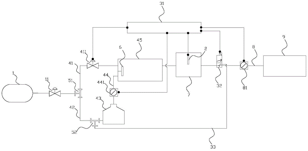
[0018] figure 1 It is a structural schematic diagram of the present invention, as shown in the figure: the flow gas humidity control device of the present invention includes a gas source 1 and a humidification system for mixing the gas from the gas source 1 into humidified gas for use in the test device 9, It also includes a humidity sensor 2 for detecting the humidity of the humidified gas and a humidification circuit system for returning the humidified gas that has not reached the standard to the humidification system for remixing; the humidified gas formed by the humidification system is transmitted to the test device 9 Humidity sensor 2 is added in the middle, the humidity sensor 2 can monitor the non-standard gas in real time, and the added humidification loop system can return the non-standard gas to the humidification system for re-mixing for test needs. This repeated use reduces the consumption of gas resources. Waste, reduce the test cost, and reduce the possibility o...


PUM


Abstract

The invention discloses a flowing gas humidity control device. The flowing gas humidity control device comprises a gas source and a humidifying system, wherein the humidifying system is used for mixing gas of the gas source into humidified gas used by a testing device. The flowing gas humidity control device further comprises a humidity sensor and a humidifying loop system, wherein the humidity sensor is used for detecting the humidity of the humidified gas, and the humidifying loop system is used for returning the humidified gas which fails to reach the standard during detection to the humidifying system for remixing. According to the flowing gas humidity control device, the additionally arranged humidity sensor can detect the gas which fails to reach the standard in real time, the additionally arranged humidifying loop system can return the gas which fails to reach the standard to the humidifying system for remixing so that the remixed gas can be used for testing needs, through the reutilization, waste of gas resources is reduced, and the testing cost is lowered; moreover, the possibility that the toxic gas which fails to reach the standard leaks is lowered, and the safety of testing operators is guaranteed.

Description

technical field [0001] The invention relates to a humidity control device, in particular to a flow gas humidity control device. Background technique [0002] In scientific research experiments, many chemical reactions need to be carried out under a flowing gas with a certain flow rate and humidity, such as the gas-solid heterogeneous photocatalytic degradation reaction in a closed container. The principle of gas-solid photocatalytic degradation is the redox reaction between the active groups on the surface of the solid catalyst and the gas degradation products. The reaction rate is affected by the number of active groups, the flow rate of gas degradation, the intensity of light, and the humidity of the environment. The gas flow rate affects the amount of pollutants on the catalyst surface per unit time, and the gas humidity not only affects the occupation of active centers on the catalyst surface, but also affects the generation of active groups. In the test of the factors ...

Claims


Application Information

Patent Timeline
IPC IPC(8): G05D22/02
Inventor 唐伯明刘晓凤何丽红曹雪娟邹晓翎黄蔚
Owner CHONGQING JIAOTONG UNIVERSITY
Why Eureka
Try Eureka