Eureka AIR delivers breakthrough ideas for toughest innovation challenges, trusted by R&D personnel around the world.

Current monitoring type electronic arc-control device

An electronic arc extinguishing and current monitoring technology, which is applied in the electrical field, can solve the problems of poor overload capacity, low reliability, and long conduction time of the arc extinguishing device, and achieve rapid arc extinguishment in the conduction time, improve reliability, and improve reliability. sexual effect

Active Publication Date: 2015-03-25
GUANGZHOU JINSHI ELECTRONICS
View PDF6 Cites 10 Cited by
  • Summary
  • Abstract
  • Description
  • Claims
  • Application Information

AI Technical Summary

Problems solved by technology

[0002] At present, in the electrical control system, mechanical switches such as contactors and relays are widely used to control the on-off of the load. However, due to the arc extinguishing grid used for ordinary arc extinguishing, it needs to pull the breaking arc to a certain length before it can work. The effect is poor, and the arc is large when the load is switched on and off, which leads to the disadvantage that the contacts are easy to burn out
[0003] For this reason, arc extinguishing devices for mechanical switch arc extinguishing have appeared, such as the patent No. CN01201907.0, named "electronic arc extinguisher"; Contactor passive switch drive controller", disclosed by the two patents, adopts the method of parallel connection of thyristor and contactor mechanical switch, the control circuit of the two patents is connected with the control terminal of the thyristor, and provides a thyristor before the contactor mechanical switch is broken. Conduction control signal, during the breaking process of the mechanical switch of the contactor, when the mechanical switch is breaking, the filter capacitor of the control circuit is discharged to delay, and the control signal for delaying the turn-on of the thyristor is turned off, the thyristor is cut off, and the arc-free breaking process is completed , since there is an uncertain delay time from the power loss of the control coil of the contactor to the breaking of the mechanical switch, in order to ensure that the thyristor is turned off after the mechanical switch is broken to ensure reliable arc extinguishing, the thyristor needs to be turned on for a long time (usually within several More than 10 milliseconds), this kind of arc extinguishing control method, which adopts the control method of delaying the closing of the control signal after the mechanical switch is broken, will inevitably increase the unnecessary and redundant conduction working time of the thyristor, and the long conduction working time of the thyristor will lead to the overload of the entire arc extinguishing device Poor capability and low reliability. At the same time, the working power of the control circuits of the above two patents must be provided by the drive circuit of the mechanical switch (which serves as the synchronization signal of the control circuit), so it is not applicable to mechanical switches without drive circuits such as circuit breakers.

Method used


Image

  • Current monitoring type electronic arc-control device
  • Current monitoring type electronic arc-control device
  • Current monitoring type electronic arc-control device

Examples


Embodiment Construction

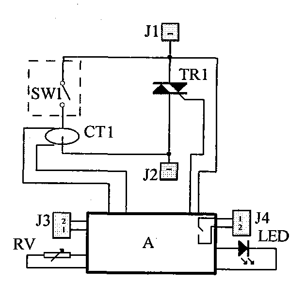
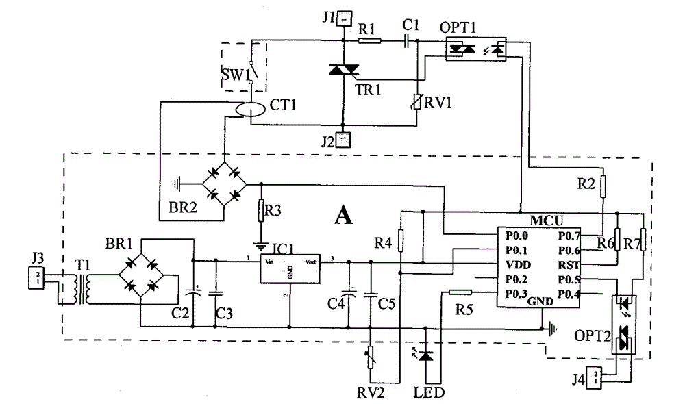
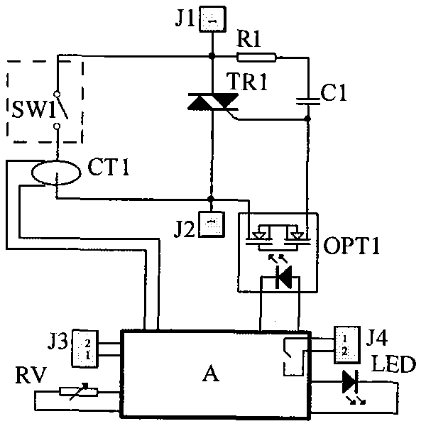
[0029] Such as figure 1 As shown, one of the embodiments of the present invention is a current monitoring electronic arc extinguishing device applied to alternating current, which includes a power semiconductor device TR1 (a thyristor, and a bidirectional thyristor) connected to a mechanical switch SW1, a mechanical switch SW1 A current sensor CT1 is connected (it is a current transformer, the figure shows that the through-heart connection can also be connected in series, and the working principle is the same), the current sensor CT1 is used to detect the current passing through the mechanical switch SW1; the output terminal of the current sensor CT1 and the power semiconductor device The control terminal of TR1 is connected to the control circuit (A), and the mechanical switch connected to this device is the mechanical switch for arc extinguishing required by SW1. The J1 and J2 terminals are the common input and output terminals connected between the power semiconductor device...


PUM


Abstract

The invention belongs to the field of electronics, and particularly discloses a current monitoring type electronic arc-control device which is suitable for the arc-control purpose for a mechanical switch. The current monitoring type electronic arc-control device comprises a power semiconductor device connected with the mechanical switch. At least one current sensor is connected with the mechanical switch and used for detecting the switch-on and switch-off of the mechanical switch. The output end of the current sensor and the control end of the power semiconductor device are connected with a control circuit. The control circuit controls the power semiconductor device to be powered off when detecting the switch-off of the mechanical switch. The current monitoring type electronic arc-control device has the advantages that the switch-on time of a thyristor is short, and reliability is high.

Description

technical field [0001] The current monitoring electronic arc extinguishing device of the present invention belongs to the field of electricity, in particular a current monitoring electronic arc extinguishing device suitable for arc extinguishing in contactors, relays, circuit breakers and other mechanical switches. Background technique [0002] At present, in the electrical control system, mechanical switches such as contactors and relays are widely used to control the on-off of the load. However, due to the arc extinguishing grid used for ordinary arc extinguishing, it needs to pull the breaking arc to a certain length before it can work. The effect is poor, and the arc is large when the load is switched on and off, which leads to the disadvantage that the contacts are easily burned. [0003] For this reason, arc extinguishing devices for mechanical switch arc extinguishing have appeared, such as the patent No. CN01201907.0, named "electronic arc extinguisher"; Contactor p...

Claims


Application Information

Patent Timeline
Patent Type & Authority Applications(China)
IPC IPC(8): H01H9/30
CPCH01H9/541H01H9/30
Inventor 郭桥石
Owner GUANGZHOU JINSHI ELECTRONICS
Why Eureka
Eureka Blog
Learn More