Multi-band antenna and terminal

A multi-frequency antenna and antenna technology, applied in the field of communication, can solve the problems of frequency band bandwidth loss and insufficient antenna bandwidth, etc., and achieve the effect of increasing bandwidth

Inactive Publication Date: 2015-03-25
ZTE CORP
View PDF7 Cites 5 Cited by
  • Summary
  • Abstract
  • Description
  • Claims
  • Application Information

AI Technical Summary

Problems solved by technology

[0003] The main technical problem to be solved by the present invention is to provide a multi-frequency antenna and terminal to solve the problem of insufficient bandwidth of the existing antenna under limited space constraints and the loss of bandwidth of some frequency bands when the bandwidth is increased

Method used


Image

  • Multi-band antenna and terminal
  • Multi-band antenna and terminal
  • Multi-band antenna and terminal

Examples


Embodiment 1

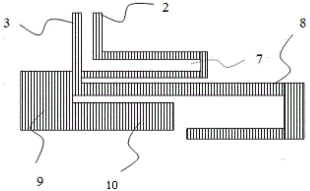
[0025] The multi-frequency antenna provided in this embodiment includes an antenna body that includes a ground portion (ie, a ground feed point), a feed portion (ie, a signal feed point), a first radiating arm and a second radiator connected to the feed portion Support arm; in this embodiment, one end of the first radiation support arm and the second radiation support arm are connected in parallel with the feeding part, and the other end extends and bends in the same direction according to the specific type of the antenna to form a corresponding type of antenna; this embodiment The antenna body in the example also includes a third radiating arm; one end of the third radiating arm is connected to the feeding part, that is, this end is connected in parallel with the first radiating arm and the second radiating arm, and the third radiating arm is The other end is connected to the grounding part, forming a loop before the feeder and the grounding part, and the formed loop can be use...

Embodiment 2

[0032] The antenna provided by the present invention can be applied to various communication terminals, such as various mobile communication terminals such as mobile phones and IPADs. In order to better understand the present invention, a specific antenna is taken as an example in conjunction with the accompanying drawings to further illustrate the present invention.

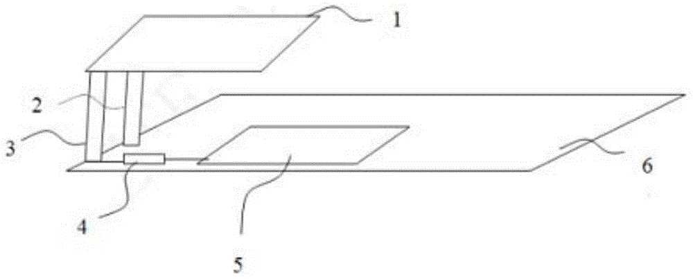
[0033] See figure 1 As shown, the antenna in this embodiment includes an antenna body 1, a matching circuit 4, a radio frequency module 5, and a main board 6. The antenna main body 1 is connected to the main board 6 through a power feeding part 3 and a grounding part 2, and the matching circuit 4 is arranged on the feeding part 3. Between the electrical part 3 and the radio frequency module 5, it is used to assist the tuning of the antenna body 1.

[0034] In this embodiment, the feeding part 3 and the grounding part 2 of the antenna body 1 are respectively connected to the edge of the main board 6; please refer to ...


PUM


Abstract

The invention discloses a multi-band antenna and a terminal. An antenna body of the multi-band antenna comprises a grounding part, a feed part, a first radiation support arm and a second radiation support arm, and further comprises a third radiation support arm, wherein the first radiation support arm and the second radiation support arm are connected with the feed part, one end of the third radiation support arm is connected with the feed part, and the other end of the third radiation support is connected with the grounding part. A loop is additionally added between the feed part and the grounding part to serve as the third radiation support arm which can be used for expanding the bandwidth frequency band so as to increase the bandwidth of the antenna, and meanwhile no bandwidth loss of part of the frequency band can be caused. In addition, the third radiation support arm can be used for assisting in tuning so that the frequency band with the better standing-wave ratio can be obtained.

Description

Technical field [0001] The present invention relates to the field of communication, in particular to a multi-frequency antenna and a terminal. Background technique [0002] The antenna is an indispensable component in the communication system, and the performance of the antenna is directly related to the quality of the received and transmitted signals. Especially in the design of communication equipment terminals, the difficulty of antennas is increasing. With the deployment and application of LTE networks, antennas need to cover a wider frequency band, and the space required is greater. However, today’s various communication terminals, especially mobile phone terminals, are becoming lighter and thinner, miniaturized, and globalized. Considering the aesthetics of the terminal, it is impossible to leave enough space for the antenna. Limited space often directly leads to insufficient bandwidth, which is also the biggest problem facing antenna design. In order to solve this proble...

Claims


Application Information

Patent Timeline
Patent Type & Authority Applications(China)
IPC IPC(8): H01Q1/38
CPCH01Q1/243H01Q5/371H01Q7/00H01Q9/0421
Inventor 李群
Owner ZTE CORP
Why Eureka
Try Eureka