Electric angle swinging motion device

A motion device, electric angular pendulum technology, applied in the direction of electromechanical devices, electric components, electrical components, etc., can solve the problems of large influence of angular positioning accuracy, high accuracy requirements, shortened service life, etc., to avoid the deviation of the angular pendulum motion center , the effect of high angular positioning accuracy and long service life

Active Publication Date: 2015-03-25
YUANYI TECH BEIJING
View PDF5 Cites 0 Cited by
  • Summary
  • Abstract
  • Description
  • Claims
  • Application Information

AI Technical Summary

Problems solved by technology

The machining of the turbine and worm group is complex, with high precision requirements, high requirements for installation and positioning, and the gap between the turbine and worm group has a great influence on the angular positioning accuracy
[0004] Secondly, the motor 5 is fixed to the bottom platform 1 by screws, and is arranged on one side. There is a large cantilever structure, and the center of the angular pendulum motion table is offset. After a long time, under the influence of its own weight, the angular positioning accuracy of the table will be reduced, and then the service life

Method used


Image

  • Electric angle swinging motion device
  • Electric angle swinging motion device
  • Electric angle swinging motion device

Examples


Embodiment Construction

[0026] The specific implementation of the electric angular pendulum motion device of the present invention will be described in detail below in conjunction with the accompanying drawings.

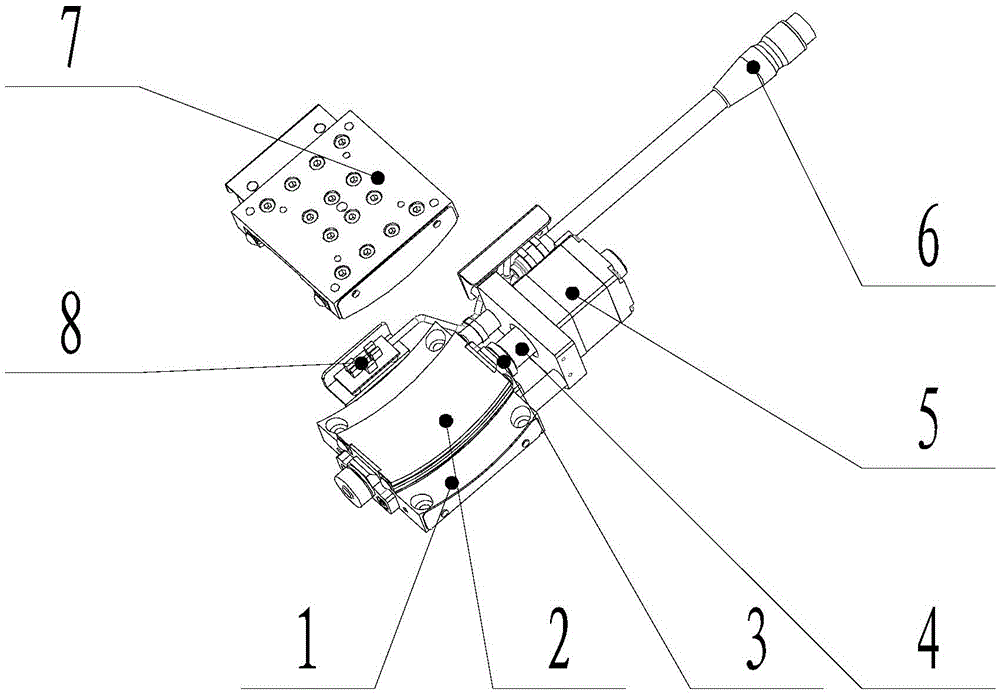
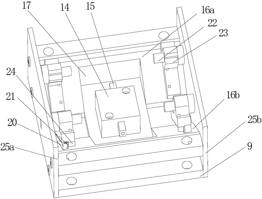
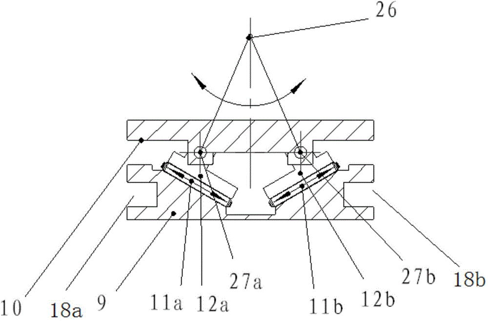
[0027] see Figure 2 to Figure 8 , the electric angular pendulum motion device of the present embodiment includes a base 9, a table top 10, at least one guide mechanism group and a driving mechanism, and the guide mechanism group includes two guide mechanisms, and each guide mechanism includes a fixed guide rail and a moving part ( 12a, 12b), respectively; the two fixed guide rails (11a, 11b) are arranged obliquely on the base 9 at an angle with the table top 10, and the two fixed guide rails (11a, 11b) of the same guide mechanism group are symmetrical Set (the plane of symmetry is the mid-section plane between the two fixed guide rails), the fixed guide rail 11a extends from the end closer to the other fixed guide rail 11b to the direction away from the base 9, and the fixed guide rail 11b...


PUM


Abstract

The invention discloses an electric angle swinging motion device. The electric angle swinging motion device comprises a base, a table board, one or more guide mechanism sets and a driving mechanism. The guide mechanism set comprises two guide mechanisms. Each guide mechanism comprises a fixed guide rail and a moving component. The moving component of each guide mechanism is connected with the fixed guide rail of the corresponding guide mechanism in a sliding mode, and the top of each moving component is connected with the bottom of the table board in a rotating mode. Two motor shaft contact parts are arranged on the bottom surface of the table board. The driving mechanism comprises a motor body and a motor shaft. The motor body can drive the motor shaft to do telescopic motion. The two ends of the motor shaft are connected with the motor shaft contact parts respectively in a floating mode. The electric angle swinging motion device has the advantages of being high in angle location accuracy and long in service life.

Description

technical field [0001] The invention relates to a mechanical device, in particular to an electric angular pendulum motion device. Background technique [0002] The existing electric angular pendulum motion device consists of a base 1, an arc-shaped guide rail 2, a worm gear group 3, a coupling 4, a motor 5, a limit switch group 8, a table top 7 and a control connection line 6, and is composed of a motion controller or The motion controller and the control computer form a motion system, which is applied to the angle adjustment of optical components or other systems that require angle adjustment. Such as figure 1 As shown: the existing electric angular pendulum motion device mostly adopts the turbine worm group 3, the function of the turbine worm group 3 is to convert the rotary motion of the motor 5 into an arc motion, and the worm of the turbine worm group 3 connects with the motor 5 through the coupling 4 Connection, the motor 5 is fixed to the bottom table 1 by screws, t...

Claims


Application Information

Patent Timeline
Patent Type & Authority Applications(China)
IPC IPC(8): H02K7/10
CPCH02K7/10
Inventor 郑煜李耀
Owner YUANYI TECH BEIJING
Why Eureka
Try Eureka