Device, system and method for detecting optical fiber routing information

An optical fiber and routing technology, applied in the direction of transmission monitoring/testing/fault measurement systems, etc., can solve the problems of consuming a lot of time and manpower and material resources, a large number of hardware, and low efficiency, so as to save manpower and material resources, fast and accurate matching process, and improve The effect of work efficiency

Inactive Publication Date: 2017-09-26
NANJING JIEDE TECH
View PDF4 Cites 0 Cited by
  • Summary
  • Abstract
  • Description
  • Claims
  • Application Information

AI Technical Summary

Problems solved by technology

[0004] At present, some operators use the ODN network intelligent management system to manage optical fiber resources, but the system needs to establish management software and be equipped with related hardware. Complexity, the amount of hardware is extremely large, resulting in high cost expenditure
People will also use fiber optic line checking instrument to manage the optical fiber network. The fiber optic line checking instrument includes two instruments, one sending and one receiving. Two people must hold one and use it at the same time. One person transmits a certain power at the computer room end, and the other person needs to use it at the user end. Location reception, the distance between two locations ranges from hundreds of meters to 20 kilometers, not only troublesome to use, but also a lot of time, manpower and material resources will be spent in the line checking process, and the efficiency is low

Method used


Image

  • Device, system and method for detecting optical fiber routing information
  • Device, system and method for detecting optical fiber routing information
  • Device, system and method for detecting optical fiber routing information

Examples


Embodiment Construction

[0033] The technical solutions provided by the present invention will be described in detail below in conjunction with specific examples. It should be understood that the following specific embodiments are only used to illustrate the present invention and are not intended to limit the scope of the present invention.

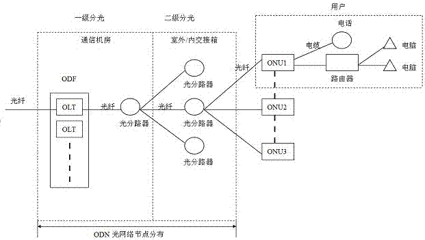
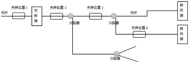
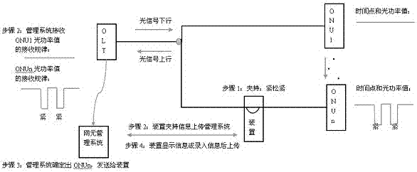
[0034] The invention provides a system for detecting optical fiber routing information, including a device for detecting optical fiber routing information and a matching management system, wherein the device for detecting optical fiber routing information is used to clamp on the optical fiber for operation. The basic structure of most optical fiber systems includes transmitting end and receiving end 1~n, and uplink and downlink optical signals are transmitted on the optical fiber. The transmitting end can obtain the optical power signal fed back by the receiving end. Specifically, we take the ONU system as an example. figure 1 It is a typical ONU system, which in...


PUM


Abstract

The invention discloses a device for detecting optical fiber routing information, which includes a mechanical clamp assembly, a clamping information acquisition module and / or a driving device, and a communication module. The mechanical clamp assembly is used to clamp and bend the optical fiber; the clamping information collection The module is used to collect the clamping rules of the mechanical fixture components; the communication module is used to transmit information, the clamping information collection module is connected to the communication module, and the driving device is used to drive the mechanical clamp components to move. The invention also discloses a system capable of detecting optical fiber routing information comprising the device and a method for detecting routing information using the system. The invention can record the clamping law of the special device by using a special device to clamp the optical fiber to make it produce optical power changes, and match the receiving end whose power change law is consistent with the change law of the optical fiber clamped by the device, thereby matching the tested optical fiber The physical geographical identification of the receiving end finally determines the user's physical routing information of the clamped optical fiber or port connection.

Description

technical field [0001] The invention belongs to the technical field of optical fiber communication, and relates to a device for detecting optical fiber routing information, and a method and system for detecting optical fiber routing information using the device. Background technique [0002] With the continuous advancement of network construction, optical fiber network has been gradually promoted and applied. Optical fiber network includes national backbone optical fiber network, inter-provincial backbone optical fiber network, provincial backbone optical fiber network, urban aggregation optical fiber network, urban access optical fiber network and other optical fiber networks, which is a huge optical fiber distribution network. Taking FTTH (fiber-to-the-home) as an example, with the development of optical fiber communication, fiber-to-the-home and 3-network integration have risen to the national strategic level, and major operators will focus on the access network level in ...

Claims


Application Information

Patent Timeline
Patent Type & Authority Patents(China)
IPC IPC(8): H04B10/07
Inventor 李建许新锋张迎春
Owner NANJING JIEDE TECH
Why Eureka
Try Eureka