Bending lower die for bending machine and manufacturing method for bending lower die

A manufacturing method and bending machine technology, applied in the field of bending machines, can solve problems such as workpiece damage, low precision, and difficulty in unloading workpieces, and achieve the effects of prolonging life, improving processing accuracy, and small friction coefficient

Active Publication Date: 2015-04-01
ANHUI LIYUAN NUMERICAL CONTROL CUTTING TOOL & PATTERNS MFG
View PDF9 Cites 5 Cited by
  • Summary
  • Abstract
  • Description
  • Claims
  • Application Information

AI Technical Summary

Problems solved by technology

[0007] Aiming at the problems in the prior art when processing a large-depth U-shaped workpiece with a flat bottom surface, the precision is low, it is difficult to remove the workpiece after processing, and it is easy to cause damage to the workpiece. The present invention provides a bending lower mold for a bending machine and its The manufacturing method, the lower mold manufactured by the method of the present invention has long service life, high machining accuracy and low manufacturing cost; the lower mold of the present invention adopts suitable materials for the characteristics of the deep U-shaped workpiece, and is designed reasonably to ensure the machining accuracy. And make the removal of the workpiece easier

Method used


Image

  • Bending lower die for bending machine and manufacturing method for bending lower die
  • Bending lower die for bending machine and manufacturing method for bending lower die
  • Bending lower die for bending machine and manufacturing method for bending lower die

Examples


Embodiment 1

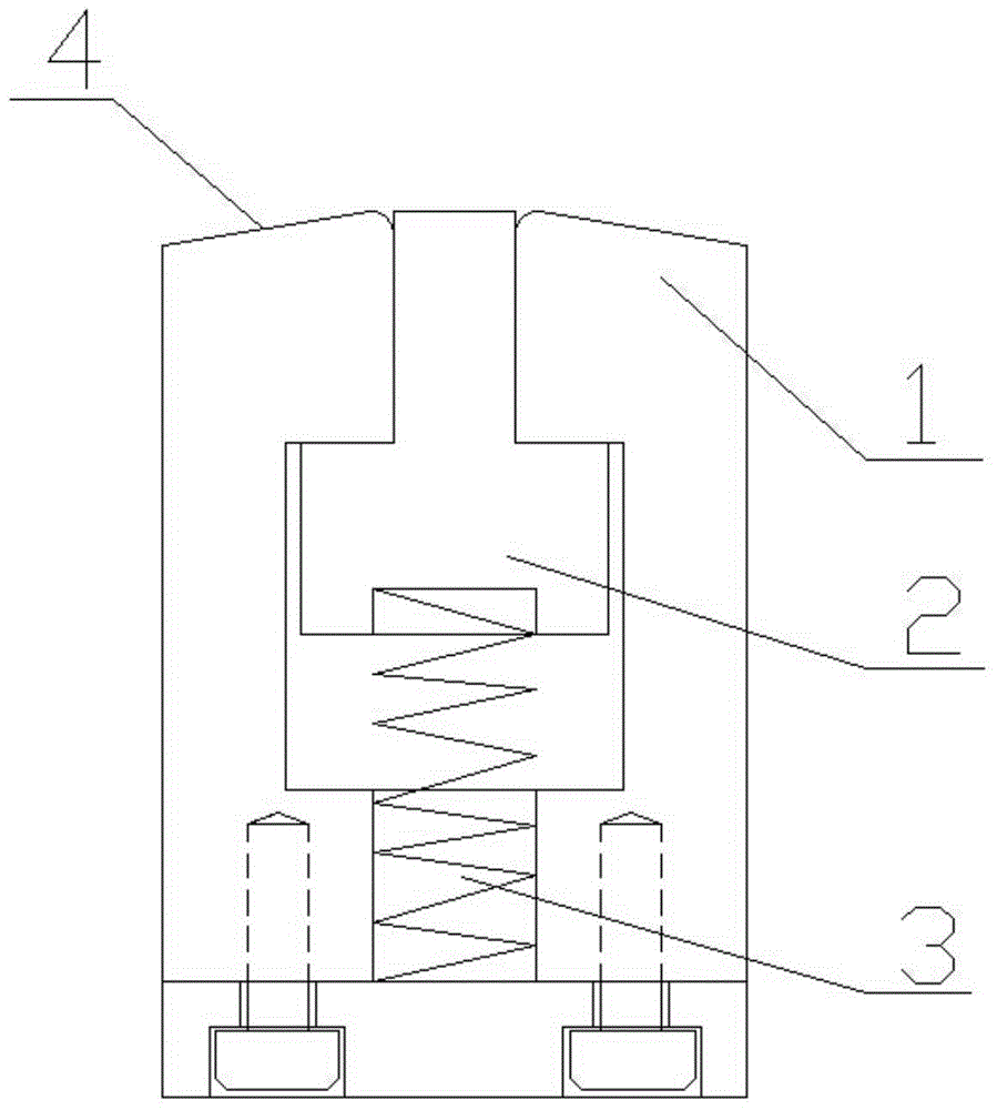
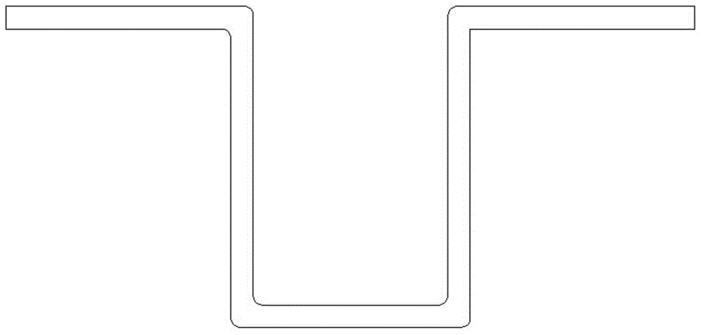
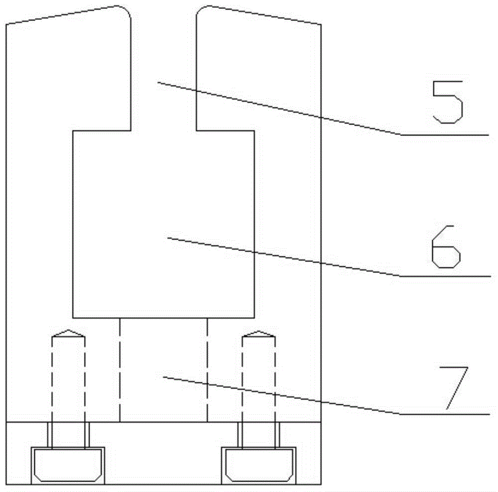
[0059] Such as figure 1 , figure 2 with image 3 As shown, a lower mold for bending a U-shaped workpiece with a processing depth of 400 mm and a width of 100 mm includes a lower mold base 1, a top block 2 at the bottom of the mold, and a discharge spring 3. The lower mold base 1 is sequentially provided with a first cavity Cavity 5, second cavity 6 and spring cavity 7; the inner surface of the first cavity 5 is provided with a wear-resistant layer, the roughness Ra of the inner surface of the first cavity 5 is 0.8, the width of the first cavity 5 is 100 mm, and the depth is 440mm; the width of the second cavity 6 is 300mm; the spring chamber 7 is arranged on the bottom surface of the second cavity 6, the quantity of the spring chamber 7 is 2, and its shape is a cylinder, and the longitudinal section width of the spring chamber 7 is 150mm The material of the top block 2 at the bottom of the mold is 40SiMn2, and the top block 2 at the bottom of the mold is an inverted T shape...

Embodiment 2

[0088] Such as figure 1 , figure 2 with image 3 As shown, a lower mold for bending a U-shaped workpiece with a processing depth of 300mm and a width of 80mm includes a lower mold base 1, a top block 2 at the bottom of the mold, and a discharge spring 3. The lower mold base 1 is sequentially provided with a first cavity Cavity 5, second cavity 6 and spring cavity 7; the inner surface of the first cavity 5 is provided with a wear-resistant layer, the roughness Ra of the inner surface of the first cavity 5 is 0.8, the width of the first cavity 5 is 80mm, and the depth is 340mm; the width of the second cavity 6 is 240mm; the spring chamber 7 is arranged on the bottom surface of the second cavity 6, the quantity of the spring chamber 7 is 8, and its shape is a cylinder, and the longitudinal section width of the spring chamber 7 is 120mm The material of the top block 2 at the bottom of the mold is 40SiMn2, and the top block 2 at the bottom of the mold is an inverted T shape. The...

Embodiment 3

[0116] Such as figure 1 , figure 2 with image 3 As shown, a lower mold for bending U-shaped workpieces with a processing depth of 200 mm and a width of 50 mm includes a lower mold base 1, a mold bottom top block 2 and a discharge spring 3, and the lower mold base 1 is sequentially provided with first hollows from top to bottom Cavity 5, second cavity 6 and spring cavity 7; the inner surface of the first cavity 5 is provided with a wear-resistant layer, the roughness Ra of the inner surface of the first cavity 5 is 0.8, the width of the first cavity 5 is 50 mm, and the depth is 240mm; the width of the second cavity 6 is 150mm; the spring chamber 7 is arranged on the bottom surface of the second cavity 6, the quantity of the spring chamber 7 is 6, and its shape is a cuboid, and the longitudinal section width of the spring chamber 7 is 75mm The material of the top block 2 at the bottom of the mold is 40SiMn2, and the top block 2 at the bottom of the mold is an inverted T shap...


PUM


Abstract

The invention discloses a bending lower die for a bending machine and a manufacturing method for the bending lower die and belongs to the field of bending machines. The invention solves the problems that the precision is low when a large-depth U-shaped workpiece with a planar bottom surface is machined and the workpiece after machining is difficultly disassembled and taken and is easy to damage in the prior art. The bending lower die comprises a lower die base, a die bottom convex piece and an unloading spring; the lower die base is sequentially provided with a first cavity, a second cavity and a spring cavity from top to bottom; the spring cavity is formed on the bottom surface of the second cavity; the cross section of the die bottom convex piece is an inverted T shape; the die bottom convex piece is arranged in the second cavity; one end of the die bottom convex piece extends into the first cavity, and the other end of the die bottom convex piece is connected with the unloading spring; the unloading spring is arranged in the spring cavity. The U-shaped workpiece with the planar bottom surface can be machined at high precision by the bending lower die, and the bending lower die has the advantages of simple structure, reasonable design and easy manufacture.

Description

technical field [0001] The invention belongs to the field of bending machines, and in particular relates to a lower bending die for a bending machine and a manufacturing method thereof. Background technique [0002] As the application of bending machines is becoming more and more extensive, more mechanical parts are expected to be processed by bending machines. However, the processing capacity of bending machines is limited by molds. Only by designing and manufacturing corresponding molds can we produce and process corresponding products. The workpiece; the processing of a deep U-shaped workpiece, such as figure 2 As shown, the bottom surface is flat, and because of the large distance from the bending point to the lowest point, it will be difficult to demould the workpiece after bending. Manual demoulding is dangerous, and machine demoulding will cause deformation of the workpiece and affect the quality of the workpiece. [0003] After searching the existing technology, it ...

Claims


Application Information

Patent Timeline
Patent Type & Authority Applications(China)
IPC IPC(8): B21D37/10B21D45/02B21D37/20
CPCB21D37/10B21D37/20B21D45/02
Inventor 张迎年张先进张一帆
Owner ANHUI LIYUAN NUMERICAL CONTROL CUTTING TOOL & PATTERNS MFG
Why Eureka
Try Eureka