Stirring head for friction stir welding capable of enhancing welding seam material mobility and manufacturing method thereof

A technology of friction stirring and material flow, applied in welding equipment, manufacturing tools, non-electric welding equipment, etc., can solve the problems of materials not being well combined, grooves, holes, and small volume of materials, so as to avoid poor flow Visible, avoid thinning, best results

Inactive Publication Date: 2015-04-01
HARBIN INST OF TECH
View PDF9 Cites 6 Cited by
  • Summary
  • Abstract
  • Description
  • Claims
  • Application Information

AI Technical Summary

Problems solved by technology

[0004] The purpose of the present invention is to solve the current friction stir welding, the material that can be transferred by the stirring pin is small and the surrounding materials cannot be well combined during the plastic flow process, and grooves are easy to appear in the weld seam , the problem of holes

Method used


Image

  • Stirring head for friction stir welding capable of enhancing welding seam material mobility and manufacturing method thereof
  • Stirring head for friction stir welding capable of enhancing welding seam material mobility and manufacturing method thereof

Examples


specific Embodiment approach 1

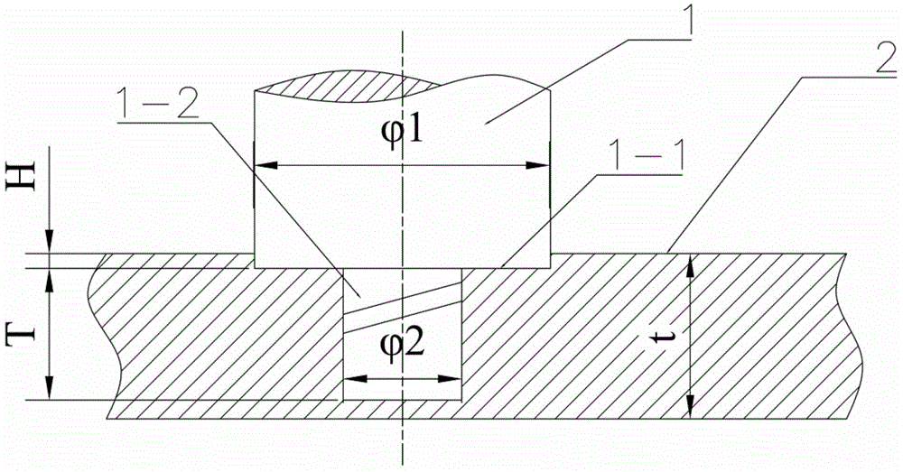
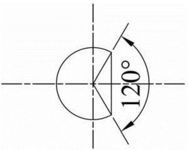
[0027] Specific implementation mode one: combine figure 1 and figure 2 Describe this embodiment, the stirring head of this embodiment comprises stirring head shoulder 1-1 and stirring needle 1-2, and stirring needle 1-2 is fixedly connected on the lower end face of stirring head shoulder 1-1, and stirring needle 1- The diameter of 2 is smaller than the diameter of the stirring head shaft shoulder 1-1, and the side of the stirring needle 1-2 is processed with a right-handed thread and a plane parallel to the axis direction, and the central angle corresponding to the cut-off arc segment of the plane is 120°. The manufacturing method of the stirring head is realized through the following steps: Step 1, determination of the size of the stirring head: determine the diameter of the upper shaft shoulder and the diameter of the stirring needle according to the thickness of the first welded workpiece 2 and the second welded workpiece 3: the shoulder The diameter φ1 is 2.75 to 3 time...

specific Embodiment approach 2

[0028] Specific implementation mode two: combination figure 1 To illustrate this embodiment, in step 1 of this embodiment, the shoulder diameter φ1 is 3 times the thickness t of the workpiece to be welded, and the diameter φ2 of the stirring pin is 1 time the thickness t of the workpiece to be welded. The size of the above stirring head can ensure the stability of the weld formation. Other steps are the same as in the first embodiment.

specific Embodiment approach 3

[0029] Specific implementation mode three: combination figure 1 To describe this embodiment, the use length T of the stirring needle in step 2 of this embodiment is 0.2 mm smaller than the thickness t of the workpiece. The above values ​​give the best results for friction stir welding. Other steps are the same as in the first embodiment.


PUM


Abstract

The invention discloses a stirring head for friction stir welding capable of enhancing welding seam material mobility and a manufacturing method thereof and relates to the stirring head and the manufacturing method thereof. The problems of defects, such as ditches and holes formed in a welding seam by a material with relatively poor mobility are solved. A device is of the structure that a stirring needle is connected to a shaft shoulder of the stirring head; right-handed threads and a plane parallel to the axial line direction are machined on the side surface of the stirring needle; the central angle corresponding to an arc section truncated from the plane is 120 degrees. The method comprises the following steps of 1, determining the size of the stirring head; 2, determining the using length of the stirring needle; 3, forming an Archimedes spiral groove with the equation that rho is equal to b plus a theta in the shaft shoulder; 4, machining the right-handed threads and the plane on the side surface of the stirring needle; 5, fixing to-be-welded workpieces; 6, positioning the stirring head; 7, performing friction stir welding on the first to-be-welded workpiece and the second to-be-welded workpiece. The stirring head is applied to friction stir welding.

Description

technical field [0001] The invention relates to a stirring head and a manufacturing method thereof, in particular to a stirring head for friction stir welding which enhances the flow of welding seam materials and a manufacturing method thereof, belonging to the field of welding technology. Background technique [0002] Since the invention of friction stir welding technology, different materials have shown different characteristics in weld formation. In addition to welding parameters affecting the quality of friction stir welding welds, the shape of the stirring head plays a very important role in the formation of friction stir welding welds. role. [0003] The stirring head is a non-consumable rotatable welding tool used in friction stir welding. During the welding process, the stirring head has the functions of generating heat by friction with the surrounding materials, breaking the oxide layer on the surface of the workpiece, and transferring plastic materials. Therefore...

Claims


Application Information

Patent Timeline
IPC IPC(8): B23K20/12
CPCB23K20/1255
Inventor 刘会杰胡琰莹赵运强刘向前王志国窦超
Owner HARBIN INST OF TECH
Why Eureka
Try Eureka