
Novel SHPB (split Hopkinson pressure bar) explosive power source device

A power source and a new type of technology, applied in measuring devices, instruments, scientific instruments, etc., can solve the problems of strong impact strength, low safety factor, and high safety factor, and achieve precise impact energy control, high impact speed, and high safety. Effect

Inactive Publication Date: 2015-04-01
QILU UNIV OF TECH
View PDF6 Cites 5 Cited by
  • Summary
  • Abstract
  • Description
  • Claims
  • Application Information

AI Technical Summary

Problems solved by technology

[0003] At present, SHPB power source devices are divided into two categories: one is to use explosives and other chemical substances to burn and explode impact bullets to produce impact effects. The advantage of this device is that it has large energy and strong impact strength. The disadvantage is that the energy is not suitable for control. Small, low safety factor, pollutes the environment
The second is to use high-pressure gas to drive the impact. The advantage of this method is that the impact energy can be better controlled and the safety factor is high, but the disadvantage is that the impact energy provided is low, and the maximum material deformation speed can be obtained. Operation Inconvenient, it needs to be equipped with high-pressure air source, and the energy supply is not easy to control accurately

Method used


Image

  • Novel SHPB (split Hopkinson pressure bar) explosive power source device
  • Novel SHPB (split Hopkinson pressure bar) explosive power source device
  • Novel SHPB (split Hopkinson pressure bar) explosive power source device

Examples


Embodiment Construction

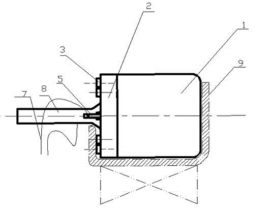
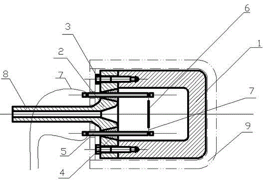
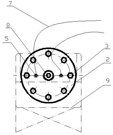
[0018] Attached Figure 1-4 This is a specific embodiment of the present invention. The SHPB new type explosive power source device of the invention includes a cylinder block 1, a cylinder cap 2, two conductive rods 5, and a wire 7. It is characterized in that the cylinder cap 2 is fixed on the cylinder block 1 by bolts 3, and the cylinder cap 2 There is a bullet launching rod 8 in the center. The bullet launching rod 8 and the cylinder cap 2 are designed as one piece. The cylinder cap 2 has two tapered through holes on both sides of the bullet launching rod 8 symmetrically, and there are rubber plugs in the through holes. 4. The conductive rod 5 is inserted into the rubber plug 4, and the two conductive rods 5 are respectively connected to the wire 7 at one end located outside the cylinder 1, and the wire 7 is connected to an external AC current source, and the end located inside the cylinder 1 passes through the wire 7 is connected to an explosive fuse 6, the large port of t...


PUM


Abstract

The invention relates to an SHPB (split Hopkinson pressure bar) explosive power source device which can accurately control impact speed / energy. The SHPB explosive power source device comprises a cylinder body, a cylinder cap, conducting rods and wires, and is characterized in that the cylinder cap is fixed on the cylinder body through bolts; a bullet launch bar is arranged at the center of the cylinder cap and is integrally designed with the cylinder cap; two conical through holes are symmetrically formed in two sides of the bullet launch bar on the cylinder cap, and rubber plugs are assembled in the conical through holes; the conducting rods are inserted on the rubber plugs; one end, located on the outer side of the cylinder body, of each conducting rod is connected with a power control system through the corresponding wire, and the other ends, located in the cylinder body, of the conducting rods are connected to an explosion fuse wire. During working, strong current is introduced to the explosion fuse wire through the wires to fuse and sublime the explosion fuse wire, high-pressure gas is generated to push a bullet to be ejected at a high speed, and explosion energy can be accurate by controlling parameters such as electric current, explosion fuse wire material and length and the like, so that the bullet impact speed is accurately controlled.

Description

Technical field [0001] The invention relates to a new type of explosive power source device for SHPB (separate Hopkinson pressure rod) device that can accurately control impact energy, is easy to operate, and is safe to use. Background technique [0002] The SHPB experimental device is an ideal tool for studying the characteristics of dynamic loads of materials. The SHPB power source device is a power drive mechanism for the launch rod of the SHPB experimental device. [0003] At present, SHPB power source devices are divided into two categories: one is the impact impact bullet produced by the combustion and explosion of explosives and other chemical substances to produce impact effects. The advantages of this device are large energy and strong impact strength. The disadvantage is that the energy is not suitable for control, and the impact is large. Small, very low safety factor, polluting the environment. The second is to use high-pressure gas to drive the impact. The advantage ...

Claims


Application Information

Patent Timeline
Patent Type & Authority Applications(China)
IPC IPC(8): G01N3/02G01N3/313
Inventor 苏国胜郭延阔杜劲
Owner QILU UNIV OF TECH
Learn More