Wave-energy energy-collecting power generation device for ships

A power generation device and wave energy technology, applied in ocean energy power generation, ship cleaning devices, hulls, etc., can solve the problems of ship stability with broken wings, increase ship roll, increase ship resistance, etc., to achieve enhanced stability and resistance Wind and wave capacity, increase the impact speed of water flow, and reduce the effect of ship rolling

Pending Publication Date: 2018-07-06
长沙紫宸科技开发有限公司
View PDF4 Cites 6 Cited by
  • Summary
  • Abstract
  • Description
  • Claims
  • Application Information

AI Technical Summary

Problems solved by technology

[0002] Ocean wave energy is the most widely distributed, clean and non-polluting renewable energy in the ocean. In recent years, there have been a variety of devices that use wave energy to generate electricity, such as nodding ducks, oscillating water columns, and valves. Most of these power generation devices are fixed, cannot be moved, and are large in size. They can only provide energy for the construction site, and cannot be used for small and medium-sized fishing boats and transport ships. A few power generation devices that can be used for ships also have wave energy utilization efficiency. Low, the stability of the ship is reduced, etc.
[0003] Chinese patent CN201310546160.1 provides an offshore scenery wave power ship, through the two reflective walls with bifurcated openings at the stern and the inner end of the reflective walls, a wave guiding surface is set to introduce wave energy into a dedicated reservoir and impact ultra-low The water head hydroelectric generator generates electricity, but there are problems such as the limited width of the stern, the induced wave energy is small, and the power generation is small, and this structure is not suitable for fishing boats and transport ships at sea.
CN201410247998.5 provides a wave energy generating device for small and medium-sized fishing boats, including wave receivers, transmission devices, conversion devices and generators connected in sequence, the wave receivers include wing plates symmetrically installed on both sides of the fishing boat and connected to the wing The flap is far away from the flap at one end of the hull. When the hull is swaying, the flap swings with the hull, and the flap moves under force in the water. The transmission device converts this motion into mechanical reciprocating motion, and the conversion device converts the mechanical reciprocating motion into rotary motion. , to drive the generator to rotate to generate electricity, but there is a small swing of the wing plate, and the movement of the loose-leaf plate in the water is smaller, coupled with multi-stage conversion, the efficiency of wave energy utilization is extremely low; it can only be used when the ship is anchored, and the use time is short , the power generation is extremely small; the power generation device brings some unsafe factors to the ship's navigation, especially when the wind and waves are strong, it is easy to cause part of the wing plate to break and seriously affect the stability of the ship.
CN201420088809.X discloses a mobile ship wave power generation device. The wave energy conversion device is symmetrically arranged on both sides of the hull. The wave energy conversion device on each side includes a main shaft and a plurality of floating bodies. The floating bodies vibrate up and down under the action of waves. The wave energy is transmitted to the main shaft through the tripod and the overrunning clutch and converted into mechanical energy, and then transmitted to the planetary power box through the main shaft, and the mechanical energy output by the planetary power box drives the generator to generate electricity. However, there are multiple floating bodies installed on the same main shaft under the action of waves. The down movement is asynchronous, and due to the existence of the overrunning clutch, only one or a few pendulum floating bodies can effectively generate electricity, and the utilization efficiency of wave energy is extremely low; when the ship is moving, the floating body will greatly increase the resistance of the ship and affect the progress of the ship. speed, waste of fuel, etc.
CN201621219164.4 provides a wave energy generating unit on a ship, including a float that can rise and fall with the waves, the float is hinged on the hull through a force arm, the force arm is connected to the piston through a transmission mechanism, and the hydraulic cylinder corresponding to the piston is set On the hull, the float rises, the connecting rod and crank drive the rocker to move up, and the piston moves upward; the float descends, and the rocker drives the piston to move downward, so that the piston reciprocates to do work, and cooperates with the hydraulic motor and generator. Realize power generation, but the floater is driven by wave energy when it rises, and it can only be driven by the gravity of the float itself when it descends, resulting in extremely low wave energy utilization or heavy floats. The potential danger of turning over increases, and at the same time, it also increases the problems of ship rolling and other problems

Method used


Image

  • Wave-energy energy-collecting power generation device for ships
  • Wave-energy energy-collecting power generation device for ships
  • Wave-energy energy-collecting power generation device for ships

Examples


Embodiment 1

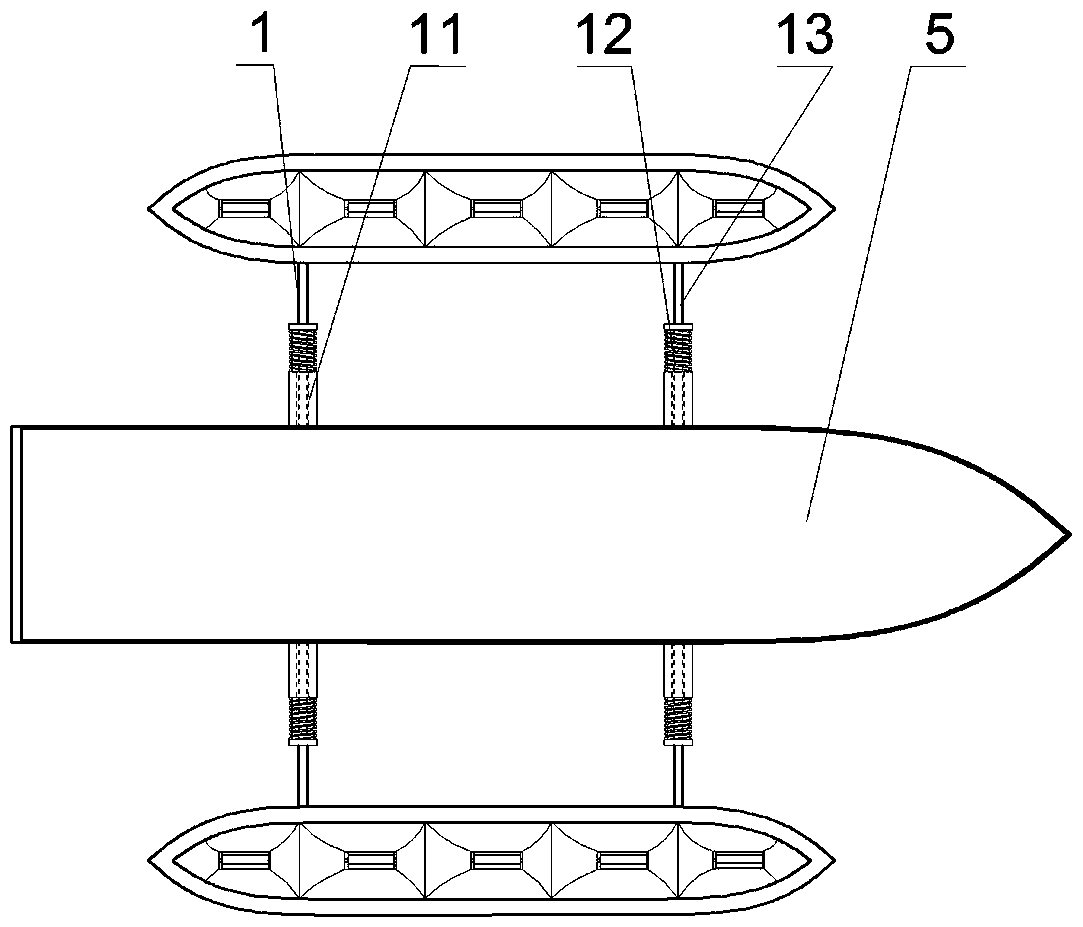
[0038] see figure 1 , figure 2 , image 3 A marine wave energy concentrating power generation device mainly includes a connecting member 1, a balanced drainage and energy concentrating mechanism 2, a protective member 3 and a power generation system. In this embodiment, the connecting member 1 is an anti-sway connecting member, and the anti-swaying connecting member includes a short strut 11, a spring 12 and a long strut 13, the short strut 11 is a hollow structure, and the short strut 11 One end is fixed on the ship 5, the other end of the short pole 11 is connected to one end of the spring 12, the other end of the spring 12 is connected to the long pole 13, and one end of the long pole 13 is inserted into the short pole 11 through the spring 12, and the long pole 13 is inserted into the short pole 11. The other end of the strut 13 is connected with the balance drainage and energy gathering mechanism 2 . When the ship 5 swayed, the spring 12 could absorb and slow down the...

Embodiment 2

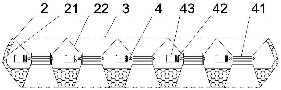
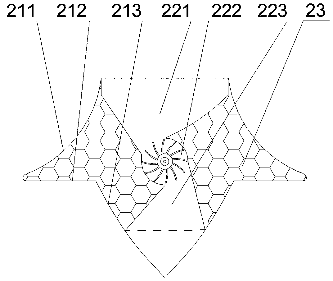
[0045] see Figure 4 , Figure 5 , Image 6 A marine wave energy concentrated power generation device mainly includes a connecting member 1, a balanced drainage and energy gathering mechanism 2, a protective member 3, and a power generation system. In this embodiment, the connecting member 1 is a fixing member, and the fixing member may be a connecting plate or a connecting rod or the like. One end of the fixing member is directly fixed on the ship 5 , and the other end of the fixing member is directly fixed on the balance drainage and energy gathering mechanism 2 . There are two balanced drainage and energy-gathering mechanisms 2, and the two balanced drainage and energy-gathering mechanisms 2 are symmetrically arranged on both sides of the ship 5 through anti-rolling connecting members, so as to improve the stability of the ship and reduce rolling. The balanced drainage and energy gathering mechanism 2 includes a balanced drainage outer casing 21 and an energy gathering a...

Embodiment 3

[0053] see figure 2 , Figure 7 , Figure 8 A marine wave energy concentrated power generation device mainly includes a connecting member 1, a balanced drainage and energy gathering mechanism 2, a protective member 3, and a power generation system. In this embodiment, the connecting member 1 is a retractable connecting member, including a strut 14 and a hydraulic cylinder 15, one end of the strut 14 is hinged on the ship 5, and the other end of the strut 14 is hinged on the balance drainage collector. On the energy mechanism 2, the middle part of the strut 14 is hinged with the piston rod of the hydraulic cylinder 15, and the cylinder body of the hydraulic cylinder 15 is hinged on the ship 5. The number of the balanced drainage and energy-gathering mechanisms 2 is two, and the two balanced drainage and energy-gathering mechanisms 2 are symmetrically arranged on both sides of the ship 5 . The hydraulic cylinder 15 pushes the balanced drainage and energy-gathering mechanism ...


PUM


Abstract

The invention discloses a wave-energy energy-collecting power generation device for ships. The wave-energy energy-collecting power generation device comprises two balanced drainage energy-collecting mechanisms, connecting components, protection components and a power generation system, wherein the two balanced drainage energy-collecting mechanisms are symmetrically arranged on the two sides of a ship body and are connected with the ship body through the connecting components; the protection components are mounted at the top end and on the bottom part of each of the balanced drainage energy-collecting mechanisms; and the power generation system is mounted in the balanced drainage energy-collecting mechanisms. According to the wave-energy energy-collecting power generation device for the ships disclosed by the invention, power is generated by adopting marine-renewable wave energy instead of fossil energy such as gasoline or diesel, so that the sailing cost of the ships is reduced, voyages of the ships can be increased, and pollution to a marine environment is reduced. By adopting the balanced drainage energy-collecting mechanisms, wave is converged and accelerated, so that water flowing kinetic energy can be effectively improved, and the power generation efficiency is promoted; and meanwhile, a water turbine is driven by bidirectionally utilizing wave energy so as to generate thepower, so that the adaptability of the power generation device on complicated and changeable marine conditions also can be improved.

Description

technical field [0001] The invention relates to the technical field of new energy, in particular to a marine wave energy gathering power generation device. Background technique [0002] Ocean wave energy is the most widely distributed, clean and non-polluting renewable energy in the ocean. In recent years, there have been a variety of devices that use wave energy to generate electricity, such as nodding ducks, oscillating water columns, and valves. Most of these power generation devices are fixed, cannot be moved, and are large in size. They can only provide energy for the construction site, and cannot be used for small and medium-sized fishing boats and transport ships. A few power generation devices that can be used for ships also have wave energy utilization efficiency. Low, the stability of the ship is reduced and other problems. [0003] Chinese patent CN201310546160.1 provides an offshore scenery wave power ship, through the two reflective walls with bifurcated openin...

Claims


Application Information

Patent Timeline
Patent Type & Authority Applications(China)
IPC IPC(8): F03B13/22B63B39/00B63B35/44B63B59/00
CPCB63B35/44B63B39/00B63B59/00B63B2035/4466F03B13/22F05B2220/706Y02E10/30
Inventor 尹小林张战锋
Owner 长沙紫宸科技开发有限公司
Why Eureka
Try Eureka