Local discharge signal identification method and device

A discharge signal and identification device technology, which is applied in the field of signal processing, can solve the problems of mistaking interference signals for partial discharge signals and low accuracy of partial discharge signals, and achieve the effect of improving accuracy

Inactive Publication Date: 2015-04-01
北京兴迪仪器有限责任公司 +1
View PDF6 Cites 12 Cited by
  • Summary
  • Abstract
  • Description
  • Claims
  • Application Information

AI Technical Summary

Problems solved by technology

[0004] Since the interference signal is also a pulse signal, the method of detecting whether the output signal of the high-voltage equipment includes a pulse signal to determine whether there is a partial discharge signal is easy to mistake the interference signal for the partial discharge signal, resulting in the accuracy of the detection of the partial discharge signal. lower

Method used


Image

  • Local discharge signal identification method and device
  • Local discharge signal identification method and device
  • Local discharge signal identification method and device

Examples


Embodiment Construction

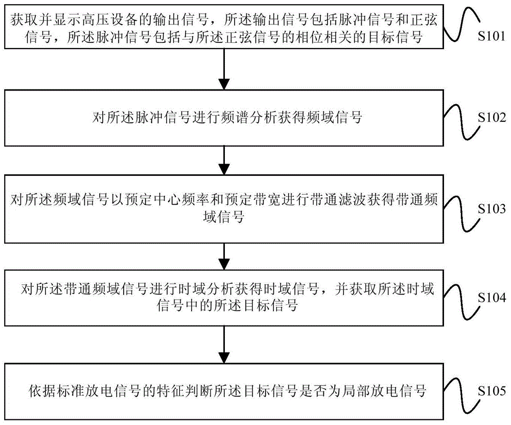
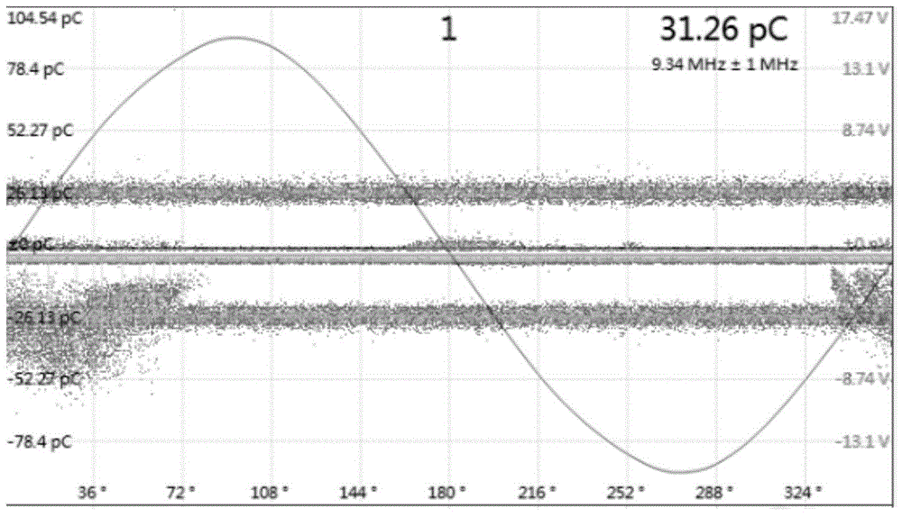
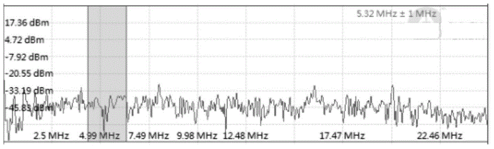
[0026] figure 1 The flow chart of the partial discharge signal identification method provided by the embodiment of the present invention; figure 2 The output signal display diagram of the high-voltage equipment provided by the embodiment of the present invention; image 3 The frequency domain signal diagram provided for the embodiment of the present invention; Figure 4 The time-domain signal diagram provided for the embodiment of the present invention; Figure 5 The waveform diagram of the target signal provided for the embodiment of the present invention. The partial discharge signal identification method provided by the embodiment of the present invention is executed by the partial discharge signal identification device, and the specific steps of the method are as follows:

[0027] Step S101, acquiring and displaying the output signal of the high-voltage equipment, the output signal includes a pulse signal and a sinusoidal signal, and the pulse signal includes a target ...


PUM


Abstract

The embodiment of the invention provides a local discharge signal identification method and device. The method comprises the following steps of obtaining and displaying an output signal of high-voltage equipment, wherein the output signal comprises a pulse signal and a sinusoidal signal, and the pulse signal comprises a target signal; carrying out spectral analysis on the pulse signal to obtain a frequency domain signal; carrying out band-pass filtering on the frequency domain signal to obtain a band-pass frequency domain signal; carrying out time domain analysis on the band-pass frequency domain signal to obtain a time domain signal, and obtaining the target signal in the time domain signal; according to the characteristics of a standard discharging signal, judging whether the target signal is a local discharging signal. According to the embodiment of the invention, the target signal and an interference signal in the pulse signal are subjected to primary separation according to the correlation of the phases of the pulse signal and the sinusoidal signal in the output signal of the high-voltage equipment, the characteristics of the target signal are compared with the characteristics of the standard discharging signal to determine whether the target signal is the local discharging signal, a phenomenon that the interference signal is wrongly taken as the local discharging signal is avoided, and detection accuracy is improved.

Description

technical field [0001] The embodiments of the present invention relate to the technical field of signal processing, in particular to a partial discharge signal identification method and device. Background technique [0002] With the rapid development of the power network and power consumption, the safe operation of the power network and power consumption has been paid more and more attention by the power system. Specific to high-voltage equipment, due to its own manufacturing defects, aging of insulating materials, or hidden dangers left over from the initial installation, partial discharge signals will be generated during operation, and the partial discharge signals are in one or several small areas of high-voltage equipment. When the discharge energy is very small, and it will not affect the insulation of high-voltage equipment in the short term, but long-term partial discharge will seriously reduce or disappear the insulation of high-voltage equipment, resulting in seriou...

Claims


Application Information

Patent Timeline
IPC IPC(8): G01R31/12
Inventor 秦旭东肖传强
Owner 北京兴迪仪器有限责任公司
Why Eureka
Try Eureka