Quick wire connector

A connector and fast technology, applied in the direction of line/collector parts, connections, electrical components, etc., can solve problems such as short circuit in wiring system, insufficient winding, safety accidents, etc., to speed up efficiency, avoid inefficiency, and insufficient protection damaged effect

Inactive Publication Date: 2015-04-01
宜宾市净源电子科技有限公司
View PDF0 Cites 3 Cited by
  • Summary
  • Abstract
  • Description
  • Claims
  • Application Information

AI Technical Summary

Problems solved by technology

Therefore, a professional electrician is usually required to operate the wiring. Firstly, the selected connected cable is stripped to expose a long enough part for mutual winding between the two cables, and then the exposed cable is The hour hand spiral is tightly wound on another cable; during operation, in order to save time, electricians usually use fingers to directly wind the cable, but often the winding is not tight enough, and the overlapped cables are easy to loosen, and there is also the use of The vise replaces the fingers to wind the cables, and the cables can be tightly wound, but when the thread of the vise is rotated and tightened, it will cause damage to the outer wall of the exposed wire end. , in a humid indoor or high temperature outdoor environment, the joint part of the cable is easily affected by external water vapor or other conductive substances, causing a short circuit in the entire wiring system and causing serious safety accidents

Method used


Image

  • Quick wire connector
  • Quick wire connector
  • Quick wire connector

Examples


Embodiment 1

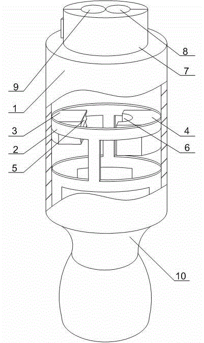
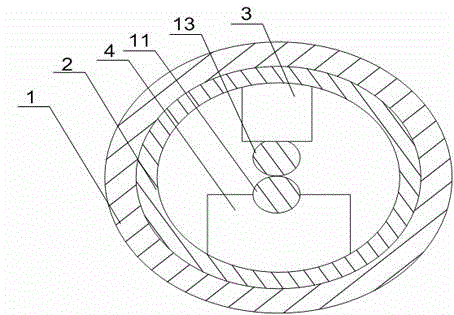
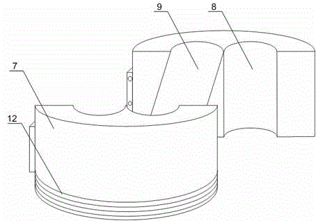
[0021] Such as Figure 1 to Figure 3 As shown, this embodiment includes a cylinder body 1 with open upper and lower ends and a screw thread on its inner wall. Two joints 7 hinged to each other are movably arranged on the upper open end of the cylinder body 1, and one joint joint 7 There are two semicircular grooves on the top of the two semicircular grooves. When the two lugs 7 are closed, two of the four semicircular grooves respectively form the through hole A8 and the through hole B9, and the axis of the through hole A8 is vertically downward, and the through hole The axis of B9 is inclined downward along the vertical direction. A rotating bracket 2 threaded with the inner wall of the cylinder body 1 is installed in the middle of the cylinder body 1. The rotation bracket 2 runs through the lower end of the cylinder body 1, and the end of the rotation bracket 2 A handle 10 is connected, and a winding block 3 and a limit block 4 are arranged symmetrically inside the rotating ...

Embodiment 2

[0023] Such as figure 1 and image 3 As shown, in this embodiment, on the basis of Embodiment 1, an external thread 12 is provided on the outer wall of the lower end of the terminal head 7 , and the two terminal heads 7 are threadedly connected to the upper open end of the cylinder body 1 . As preferably, the threaded connection between the terminal head 7 and the cylinder body 1 is convenient for the quick separation of the wire head and the device after the two wire cores are entangled with each other, and the speed of connection is accelerated. Meanwhile, the threaded connection can also make the wire cores in the mutual Prevent the cable from rotating when winding, and avoid unstable connection of the entire wiring system.

[0024]The rotating bracket 2 includes an upper ring and a lower ring that are connected to each other and arranged at intervals. The upper ring and the lower ring are respectively screwed to the inner wall of the cylinder body 1. The winding block 3 a...


PUM


Abstract

The invention discloses a quick wire connector which comprises a barrel, wherein two mutually hinged connector lugs are movably arranged at the upper open end of the barrel; two of four semicircular grooves form a through hole A, and the other two of the four semicircular grooves form a through hole B; the axial line of the through A is vertically downward; the axial line of the through hole B is downwards inclined in the vertical direction; a rotating bracket in threaded fit with the inner wall of the barrel is mounted at the middle of the barrel; a handle is connected to the tail end of the rotating bracket; a plurality of arc-shaped grooves of which the axial directions are the same as that of the through hole B are formed in the sidewall, close to the center of the rotating bracket, of a winding block; a limiting groove is formed in the outer wall of the side, opposite to the arc-shaped grooves, of a limiting block. According to the quick wire connector, low efficiency and high-intensity working load during manual coil winding directly with fingers are avoided, damage to the outer wall of a wire core when a worker rotates the wire core with a vice is reduced, cables can be quickly connected, and meanwhile, the wire core is protected from being damaged.

Description

technical field [0001] The invention relates to the field of power systems, in particular to a quick connector. Background technique [0002] Indoor cable wiring usually adopts hidden wiring layout, and in order to ensure the safety and specification of wiring during wiring, many guidelines should be followed. For example, when the power line is buried in the wall, ceiling, floor or floor tiles, it must wear a PVC pipe. The wires should not have knots and kinks in the pipe. When the load-bearing wall does not allow deep grooves, the sheathed line can be directly buried; The connecting pipeline of the inner lamp position can use a hose wire, and the threading in the protection tube must be able to be twitched and replaced; the bending part of the wire protection tube should use a matching bending tool or a matching elbow, and there should be no wrinkles; when the power line needs to be branched ground, a junction box, etc. should be used. [0003] In the wiring process, it ...

Claims


Application Information

Patent Timeline
Patent Type & Authority Applications(China)
IPC IPC(8): H01R43/033
CPCH01R43/033
Inventor 杨洪杨富智
Owner 宜宾市净源电子科技有限公司
Why Eureka
Try Eureka