Hydraulic screw crawler hiller

A hydraulic and crawler technology, applied in the field of hydraulic screw crawler soil cultivator, can solve the problems of large volume, complex mechanical structure, inconvenient adjustment, etc., and achieve the effect of strong versatility and easy adjustment and operation

Inactive Publication Date: 2015-04-08
HUNAN TOBACCO CHENZHOU
View PDF6 Cites 2 Cited by
  • Summary
  • Abstract
  • Description
  • Claims
  • Application Information

AI Technical Summary

Problems solved by technology

Therefore, the two sets of transmissions need to reduce the rotational speed by 1/10 and 1/6 respectively, and the deceleration parts of the two sets of trans

Method used


Image

  • Hydraulic screw crawler hiller
  • Hydraulic screw crawler hiller
  • Hydraulic screw crawler hiller

Examples


Embodiment Construction

[0064] In order to make the technical means, creative features, goals and effects achieved by the present invention easy to understand, the present invention will be further described below in conjunction with specific illustrations.

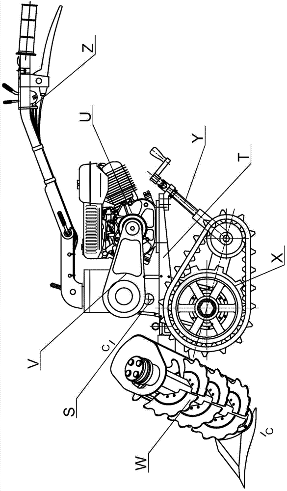
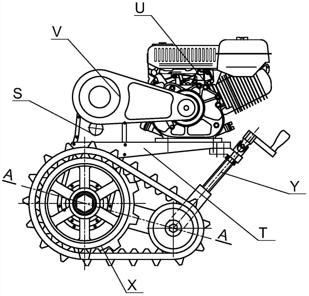
[0065] see Figure 1 ~ Figure 2 The hydraulic screw-type crawler earth cultivator includes chassis support part T, engine part U, power transmission part V, variable speed steering control part S, crawler walking part X, operation adjustment part Y, soil cultivating mechanism W, and hand-operated operation part Z; Among them, the engine part U, the variable speed steering control part S, the soil cultivation mechanism W, and the hand-held operation part Z are installed on the chassis support part T, and the power transmission part V is connected to the engine part U and the variable speed steering control part S for power transmission. Part of the power is driven by the variable speed steering control part S to drive the crawler walking part X t...


PUM


Abstract

The invention discloses a hydraulic screw crawler hiller. A motor part, a speed-change and steering control part, a hilling working mechanism, and a hand-held operation part are arranged on a chassis bracket part of the hiller. The speed-change and steering control part is connected with a crawler travelling part and the hilling working mechanism. In the hilling working mechanism, a left side hilling blade assembly and a right side hilling blade assembly have a same structure, and are symmetrically arranged on two ends of a bracket assembly, relative to a power transmission case which is arranged on the bracket assembly. A left side breadth adjustment mechanism and a right side breadth adjustment mechanism are arranged on the bracket assembly. A left hydraulic driving part and a right hydraulic driving part are connected with the power transmission case. The hilling working mechanism is positioned between two ridges. While screw conveying hilling is carried out, a weeding function is performed. The hilling working mechanism is controlled by a hydraulic pump-motor direct connection system, such that versatility is high. Crawler driving is adopted in the crawler travelling part, such that vehicle trafficability is effectively improved. A working device transmission function is integrated in the speed-change and steering control part, such that the total weight of the hiller can be reduced.

Description

technical field [0001] The invention relates to the technical field of agricultural machinery, in particular to a hydraulic screw crawler cultivator. Background technique [0002] At present, most of the cultivators are driven by rubber wheels. However, due to the light weight of the cultivator, after entering the field, the ground adhesion is small. When the resistance increases, the driving wheel is easy to slip. When working in the field, the driving rubber wheel is usually changed to an iron driving wheel. The convex teeth of the iron driving wheel in the circumferential direction are inserted into the soil deeply, which can improve adhesion and prevent slipping; but the convex teeth of the iron driving wheel At the same time, it will damage the ditch surface at the bottom of the mud, which is not conducive to the drainage of the field. When walking on the road, due to the large circumferential gap between the convex teeth, the driving wheel contacts the ground in a poly...

Claims


Application Information

Patent Timeline
IPC IPC(8): A01B49/02B62D55/08F16H3/08F16H63/30
Inventor 何阳曹健张建文陈洪浪李永刚王灿廖胜利
Owner HUNAN TOBACCO CHENZHOU
Why Eureka
Try Eureka