Al technical title is built by PatSnap Al team. It summarizes the technical point description of the patent document.
A technology of inkjet printers and plastic tubes, applied in typewriters, printing devices, printing, etc., can solve problems such as affecting the appearance and spraying position deviation, and achieve the effects of prolonging the working cycle, achieving support, and high precision
Inactive Publication Date: 2015-04-08
SHANDONG JIANZHU UNIV
View PDF7 Cites 10 Cited by
Summary
Abstract
Description
Claims
Application Information
AI Technical Summary
This helps you quickly interpret patents by identifying the three key elements:
Problems solved by technology
Method used
Benefits of technology
Problems solved by technology
However, due to the twisting of the plastic tube during the injection molding process, it often leads to a deviation in the spraying position of the mark, which affects the appearance
Therefore, plastic pipe manufacturers urgently need a coding device that can automatically correct the position of the spray mark, but there is no such device on the market
Method used
Image
Click on the blue label to locate the original text in one second.
Reading with bidirectional positioning of images and text.
Examples
Embodiment Construction
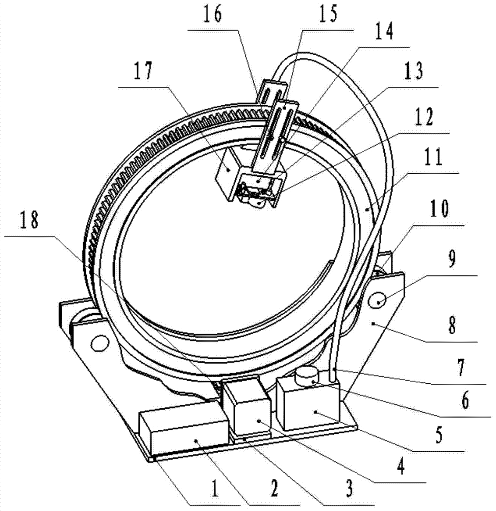
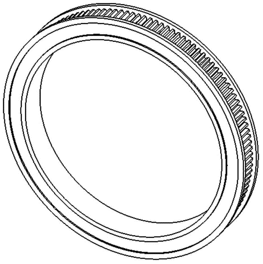
[0011] A plastic tube inkjet printer consists of a base plate 1, a controller 2, a motor bracket 3, a stepping motor 4, an ink tank 5, a micropump 6, an ink delivery tube 7, a vertical plate 8, a shaft 9, a bearing 10, and a turntable 11. CCD12, ink cartridge circuit board 13, ink cartridge 14, adjustment plate 15, adjustment screw 16, ink cartridge bracket 17, pinion 18, is characterized in that: bottom plate 1 is at the bottom of the entire device, vertical plate 8, motor bracket 3, The controller 2 and the ink barrel 5 are installed on the base plate 1, the stepping motor 4 is installed on the motor support 3, the pinion 18 is installed on the shaft of the stepping motor 4, and the center of the outer edge of the rotating disk 11 has a tooth arc. The tooth arc has the same modulus as the pinion 18, and is meshed for transmission. The shaft 9 is installed on a bracket composed of two vertical plates 8, and a bearing 10 is installed on the shaft 9. The outer surface of the bea...
PUM
Abstract
A plastic pipe inkjet printer belongs to the field of light industry printing. The plastic pipe inkjet printer is composed of a bottom plate, a controller, a motor bracket, a stepper motor, an ink barrel, a micro pump, an ink conveying pipe, vertical plates, a shaft, a bearing, a turntable, a CCD, a cartridge circuit board, a cartridge, adjusting plates, adjusting screws, a cartridge bracket, and a small gear. The plastic pipe inkjet printer is characterized in that the bottom plate is disposed at the bottom of the whole equipment; the vertical plates, the motor bracket, the controller and the ink barrel are mounted on the bottom plate; the stepper motor is mounted on the motor bracket; the small gear is mounted on the steppe motor and is in meshed transmission with the toothed arc of the turntable; the shaft is mounted on a bracket formed by the two vertical plates and is equipped with the bearing, and the outer surface of the bearing contacts the toothed arc of the turntable; the cartridge, the cartridge circuit board, the adjusting plates and the CCD are mounted on the cartridge bracket; the adjusting plates are mounted on the turntable through the adjusting screws; the micro pump is mounted on the ink barrel; and the ink conveying pipe is mounted between the micro pump and the cartridge. By adopting the inkjet printer, the inkjet printing position of a plastic pipe can be automatically tracked and adjusted.
Description
technical field [0001] The invention relates to a plastic tube inkjet printer, in particular to an inkjet printer for plastic tubes which uses an ordinary ink cartridge and can automatically correct the inkjet position, and belongs to the field of marking equipment. Background technique [0002] The inkjet printer is widely used in the production of plastic pipes, etc. Its main function is to spray-paint the factory name, specifications, contact information and other marks on the outer surface of the plastic pipe. At present, there are many types of plastic pipes, one of which is longitudinally shaped with stripes of different colors, and the marks of the manufacturer are required to be sprayed on one side of the stripes. However, due to the twisting of the plastic tube during the injection molding process, it often leads to a deviation in the spraying position of the mark, which affects the appearance. Therefore, plastic pipe manufacturers are in urgent need of a coding de...
Claims
Application Information
Patent Timeline
Application Date:The date an application was filed.
Publication Date:The date a patent or application was officially published.
First Publication Date:The earliest publication date of a patent with the same application number.
Issue Date:Publication date of the patent grant document.
PCT Entry Date:The Entry date of PCT National Phase.
Estimated Expiry Date:The statutory expiry date of a patent right according to the Patent Law, and it is the longest term of protection that the patent right can achieve without the termination of the patent right due to other reasons(Term extension factor has been taken into account ).
Invalid Date:Actual expiry date is based on effective date or publication date of legal transaction data of invalid patent.