Electric bypass valve device

A bypass valve, electric technology, applied in transportation and packaging, power steering mechanism, steering mechanism, etc., can solve the problems of inability to adapt to multi-level changes in steering assistance, high precision requirements for electromagnetic proportional valves, and single output assistance characteristic curve. , to improve the control stability and safety, solve the problem of fluttering, and enhance the feel

Inactive Publication Date: 2015-04-08
JIANGSU UNIV
View PDF9 Cites 4 Cited by
  • Summary
  • Abstract
  • Description
  • Claims
  • Application Information

AI Technical Summary

Problems solved by technology

However, due to the use of a single solenoid valve, the scheme has a single output assist characteristic curve, which cannot meet the requirements of multi-level changes in steering assist.
Its solenoid valve only has two states of switch, and the excessive process of switching the switch state of the solenoid valve at high and low speeds will cause problems such as hydraulic vibration and noise.
Chinese patent 201110367078.3, titled "A Double Solenoid Valve Device", proposes combined control of the open and closed states of the two solenoid valves in the double solenoid valve device to achieve flow regulation in the bypass oil circuit, but this solution can only Realize four different bypass flow modes, output four booster characteristic curves, cannot continuously adjust the bypass oil volume, and change the booster effect with speed
In Chinese patent 200820227155.9, an electromagnetic proportional valve is used to adjust the opening of the bypass branch to control the flow of hydraulic oil. However, this solution has higher requirements for the accuracy of the electromagnetic proportional valve itself and stricter requirements for the controller.
In actual use, the patent uses a needle-type electromagnetic proportional valve to control the flow rate, and the needle valve usually cannot withstand high pressure in actual use and the phenomenon of opening instability occurs, so there are many disadvantages

Method used


Image

  • Electric bypass valve device
  • Electric bypass valve device
  • Electric bypass valve device

Examples


Embodiment Construction

[0026] The present invention will be further described below in conjunction with the accompanying drawings and specific embodiments, but the protection scope of the present invention is not limited thereto.

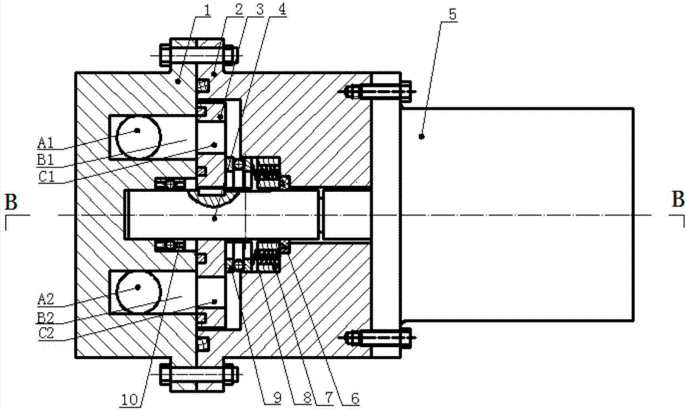
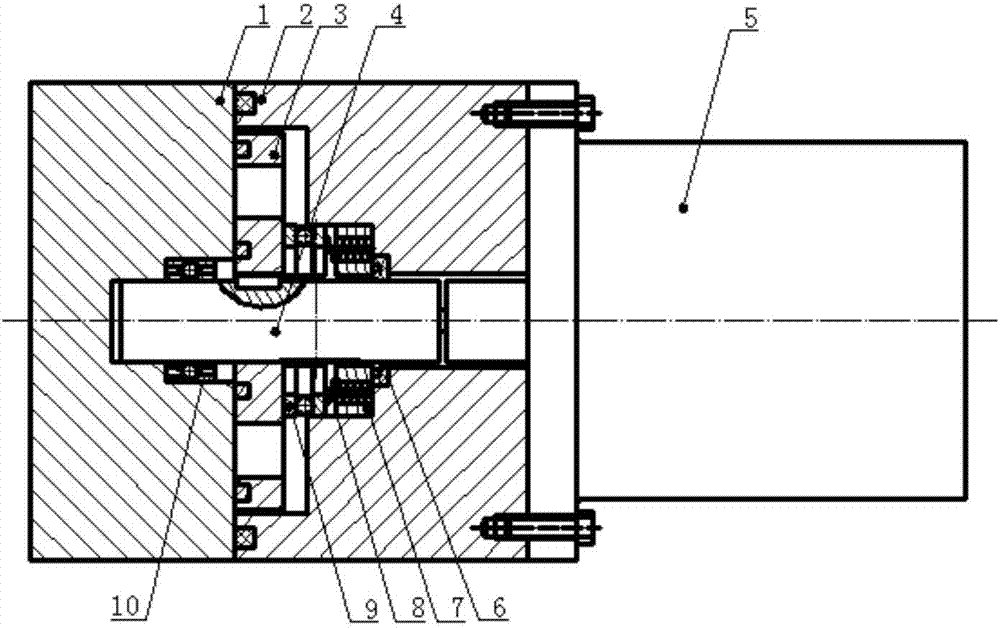
[0027] Such as figure 1 , 2 As shown, the electric bypass valve device of the present invention includes a first valve body 1, a second valve body 2, a rotating shaft 4 and a stepping motor 5; the rotating shaft 4 is connected to the output end of the stepping motor 5, and the The second valve body 2 and the first valve body 1 are sequentially installed on the rotating shaft 4 , and a bearing 10 is arranged between the first valve body 1 and the rotating shaft 4 . Both ends of the second valve body 2 are respectively connected to the first valve body 1 and the stepping motor 5 through bolts. The end surface of the second valve body 2 in contact with the first valve body 1 is provided with a ring groove for placing a sealing ring to prevent oil leakage.

[0028] Such as...


PUM


Abstract

The invention provides an electric bypass valve device. The electric bypass valve device comprises a first valve body, a second valve body, a rotating shaft and a stepper motor, wherein two oil way holes are formed in the first valve body; and an oil control disk is placed between the second valve body and the first valve body, and is provided with two comma-shaped oil holes. The stepper motor drives the oil control disk to rotate through the rotating shaft according to a control signal to change the valve opening overlap area between the two comma-shaped oil holes and the two oil way holes of the first valve body so as to change the oil flow of a bypass oil way, so that a power steering gear outputs different steering assisting powers as required when a vehicle is steered under the working condition of different vehicle speeds. The device can realize the adjustment of the assisting powers of the power steering gear along with the speeds, can output different assisting power characteristic curves to enhance the driver hand feel in high-speed driving, has the advantages of simple structure, lower cost and easy control, and improves the control stability and safety in vehicle driving.

Description

technical field [0001] The invention belongs to the field of auto parts, in particular to an electric bypass valve device. Background technique [0002] With the advancement of science and technology and the continuous development of the automobile industry, people have higher and higher requirements for the performance of vehicles, and at the same time, they also put forward higher requirements for the maneuverability and safety of vehicles. At this stage, the traditional hydraulic power steering is widely used in medium and heavy vehicles. Although it can provide good power assist at low speeds and the steering is relatively light, as the vehicle speed increases, the power provided by the hydraulic power steering is also increasing. When the vehicle speed is very high, the power boost is very large. At this time, the driver loses a good sense of the road, causing the problem of "floating", which reduces the safety of high-speed driving. [0003] The power assist character...

Claims


Application Information

Patent Timeline
Patent Type & Authority Applications(China)
IPC IPC(8): B62D5/065
CPCB62D5/065B62D5/08B62D5/091
Inventor 耿国庆江浩斌陈龙龚晓庆刘涛唐斌刘海夏磊
Owner JIANGSU UNIV
Why Eureka
Try Eureka