Transfer case

A turnover box and box body technology, applied in the direction of internal accessories, etc., can solve the problem that parts are easy to be hung up or scratched, and achieve the effect of being easy to be hung up or scratched

Active Publication Date: 2015-04-08
HENAN PINGGAO ELECTRIC +2
View PDF6 Cites 3 Cited by
  • Summary
  • Abstract
  • Description
  • Claims
  • Application Information

AI Technical Summary

Problems solved by technology

[0006] The purpose of the present invention is to provide a turnover box, which aims to solve the problem in the prior art that the surface of parts is easy to be hung up or scratched before and after the transfer process

Method used


Image

  • Transfer case
  • Transfer case
  • Transfer case

Examples


Embodiment Construction

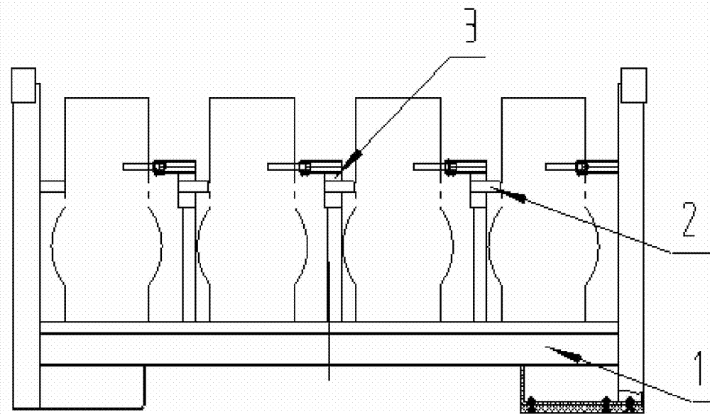
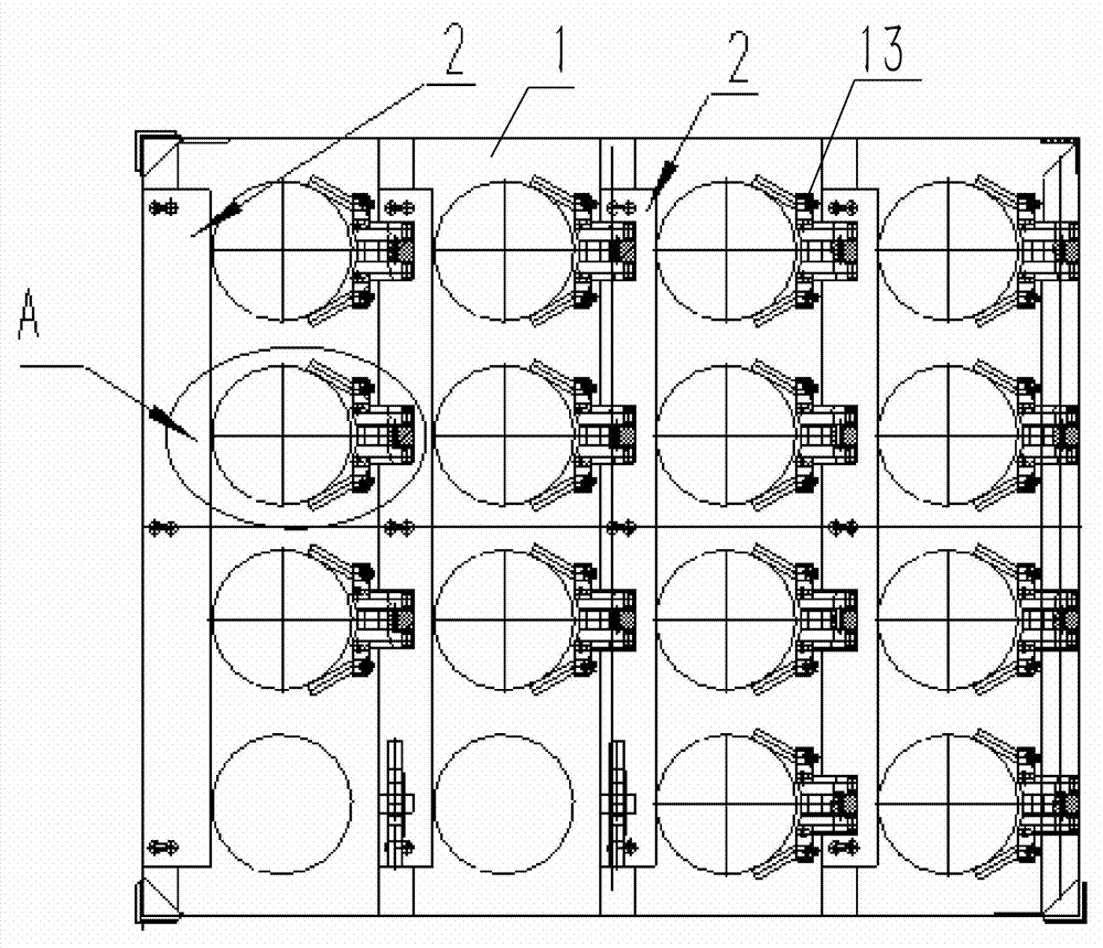
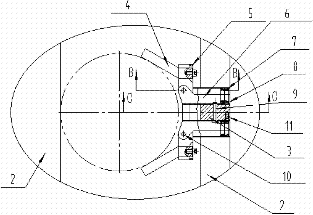
[0034] The embodiment of turnover box among the present invention: as Figure 1 to Figure 15 As shown, the turnover box is a turnover box with an anti-dumping mechanism, which is mainly composed of a box body, a mechanical claw 12 and a baffle plate 2. The box body includes a frame 1 at the bottom and plate-shaped or shelf-shaped spacers fixed thereon and arranged at intervals from left to right. The edge of the frame 1 is fixed with a surrounding plate that surrounds the periphery of each spacer. The plate is higher than the spacer, and the top of the spacer is provided with support blocks 3 uniformly spaced from front to back and a baffle 2 snap-connected to the support block 3, and the left edge of the baffle 2 is provided with four The support block 3 matches the installation slot of the buckle, the right edge of the baffle plate 2 protrudes from the right side of the spacer, and the support block 3 protrudes from the upper side of the baffle plate 2 . The mechanical claw...


PUM


Abstract

The invention discloses a transfer case. Mechanical claws are assembled in a case body of the transfer case, so that components can be clamped in the case body by the mechanical claws when transferred; clamping force can be applied to two reverse sides of each component by two claw bodies of the corresponding mechanical claw, accordingly, supporting effects can be realized for the components in the case body by the mechanical claws, and the components can be prevented from being toppled over along with jolting of the case body; the two claw bodies of each mechanical claw can be oppositely opened and closed from the periphery of the corresponding component to clamp the component when the two claw bodies of the mechanical claw are operated to clamp the component, so that the claw bodies of the mechanical claws can be prevented from frictionally sliding on the surfaces of the components when the components are clamped by the mechanical claws, and the surfaces of the components can be prevented from being scratched. The transfer case has the advantages that the components can be clamped under the oppositely opened and closed actions of the claw bodies of the mechanical claws and can be prevented from being toppled over owing to the component supporting effects of the claw bodies, and accordingly the problem that the front and rear surfaces of components can be easily suspended or scratched in transferring procedures in the prior art can be solved.

Description

technical field [0001] The invention relates to a turnover box. Background technique [0002] At present, when transporting parts with coating or plating on the surface, it is usually necessary to pack these parts into a turnover box for transportation. At the same time, in order to avoid damage to the coating or plating on the parts, the The parts usually need to be arranged in the box at intervals from each other, which makes there will be a gap between the parts in the turnover box that can shake. In order to avoid the bumping phenomenon caused by the shaking of the parts, the commonly used processing methods are as follows Two kinds: [0003] 1. Removably fix each component in the weekly packing box, such as through flange connection, buckle connection, etc., but in this way, the parts inevitably need to be connected with the turnover box through fasteners, and the During the process, with the bumping of the turnover box, these fasteners often loosen, causing the parts...

Claims


Application Information

Patent Timeline
IPC IPC(8): B65D25/10B65D25/04
Inventor 张子明高伟翟志伟段冲李伟奇杨帆唐小兰时小广
Owner HENAN PINGGAO ELECTRIC
Why Eureka
Try Eureka