High efficiency and energy saving blowback device used for gas turbine air inlet system

An air intake system, high-efficiency and energy-saving technology, applied in gas turbine devices, jet propulsion devices, mechanical equipment, etc., can solve problems such as waste of compressed air source and energy, poor injection effect, and reduced working efficiency of air filtration systems. The effect of working time, improving work efficiency, saving energy and air supply

Inactive Publication Date: 2015-04-08
CHENGDU BOOST ENERGY TECH
View PDF10 Cites 6 Cited by
  • Summary
  • Abstract
  • Description
  • Claims
  • Application Information

AI Technical Summary

Problems solved by technology

[0013] The present invention provides a high-efficiency and energy-saving back-blowing device for gas turbine intake systems in order to solve the problems of poor blowing effect of the back-blowing device in the prior art, waste of compressed air source and energy, and reduction of the working efficiency of the entire air filtration system , ...

Method used


Image

  • High efficiency and energy saving blowback device used for gas turbine air inlet system
  • High efficiency and energy saving blowback device used for gas turbine air inlet system

Examples


Embodiment 1

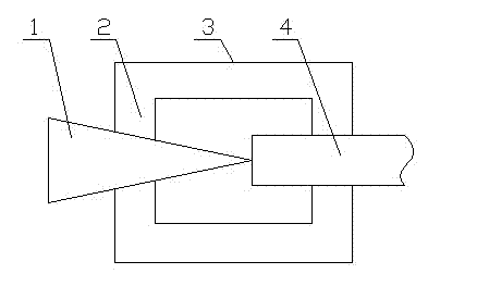
[0039] The high-efficiency and energy-saving blowback device for the gas turbine intake system of the present embodiment includes a blowback pipe communicated with a compressed air source through a pipeline, and also includes a conical flow guiding device, the center line of the flow guiding device and the center of the blowback pipe Lines are on the same straight line, the center line of the flow guide device is on the same line as the center line of the air filter cartridge; the top of the flow guide device is flush with the end face of the blowback pipe or the top of the flow guide device extends into Inside the blowback pipe; the bottom surface of the flow guiding device is facing the center of the air filter cartridge.

Embodiment 2

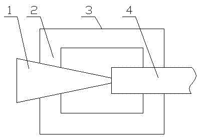
[0041] The high-efficiency and energy-saving blowback device for the gas turbine intake system of the present embodiment includes a blowback pipe communicated with a compressed air source through a pipeline, and also includes a frustum-shaped flow guide, and the center line of the flow guide is connected to the center of the blowback pipe. line on the same straight line, the centerline of the guide device and the center line of the air filter cartridge are on the same straight line; the upper bottom surface (end face with smaller radius) of the guide device is flush with the end face of the blowback pipe Or the upper bottom surface (end surface with larger radius) of the flow guide device extends into the blowback pipe; the lower bottom surface (end surface with larger radius) of the flow guide device is facing the center of the air filter cartridge.

Embodiment 3

[0043] The high-efficiency and energy-saving blowback device for the gas turbine intake system of the present embodiment includes a blowback pipe communicated with a compressed air source through a pipeline, and also includes a conical flow guiding device, the center line of the flow guiding device and the center of the blowback pipe Lines are on the same straight line, the center line of the flow guide device is on the same line as the center line of the air filter cartridge; the top of the flow guide device is flush with the end face of the blowback pipe or the top of the flow guide device extends into Inside the blowback pipe; the bottom surface of the flow guiding device is facing the center of the air filter cartridge; the flow guiding device is connected with the blowback pipe through a fixing device.


PUM


Abstract

The invention belongs to the technical field of a gas turbine, and discloses a high efficiency and energy saving blowback device used for a gas turbine air inlet system which is used for solving the problems of poor blowing effect, compressed air source and energy waste, and reduction of the working efficiency of the whole air filtration system of a blowback device in the prior art. The high efficiency and energy saving blowback device includes a blowback pipe which is communicated with a compressed air source by a pipe, also includes a conical guiding device, the center line of the guiding device and the center line of the blowback pipe are in the same straight line, the center line of the guiding device and the center line of an air filter filtering cartridge are in the same straight line, the top of the guiding device and the end surface of the blowback pipe are flushed, or the top of the guiding device stretches into the blowback pipe, and the bottom surface of the guiding device just faces toward the center of the air filter filtering cartridge.

Description

technical field [0001] The invention belongs to the technical field of gas turbines, and in particular relates to a high-efficiency energy-saving reverse blowing device used in gas turbine intake systems. Background technique [0002] A gas turbine is a rotary power machine that converts heat energy into mechanical work using continuously flowing gas as a working medium. In the main process of air and gas, the gas turbine cycle is mainly composed of three major components: the compressor, the combustion chamber and the gas turbine. [0003] The compressor inhales air from the external atmosphere, and pressurizes it step by step through the axial flow compressor, and the air humidity is also increased accordingly; the compressed air is sent to the combustion chamber to mix with the injected fuel to produce high-temperature and high-pressure gas Then enter the turbine to expand and do work, and push the turbine to drive the compressor and the external load rotor to rotate at ...

Claims


Application Information

Patent Timeline
IPC IPC(8): F02C7/055B01D46/24B01D46/42
Inventor 党为民李如荣景君陈华
Owner CHENGDU BOOST ENERGY TECH
Why Eureka
Try Eureka